Power controlling apparatus

Inactive Publication Date: 2005-05-19
MITSUBISHI ELECTRIC CORP
View PDF12 Cites 2 Cited by
  • Summary
  • Abstract
  • Description
  • Claims
  • Application Information

AI Technical Summary

Problems solved by technology

Therefore, there was a problem in that power generation operation accompanying great power cannot be continued for a long period.
That is, since the ON-vo

Method used


Image

  • Power controlling apparatus
  • Power controlling apparatus
  • Power controlling apparatus

Examples


embodiment 1

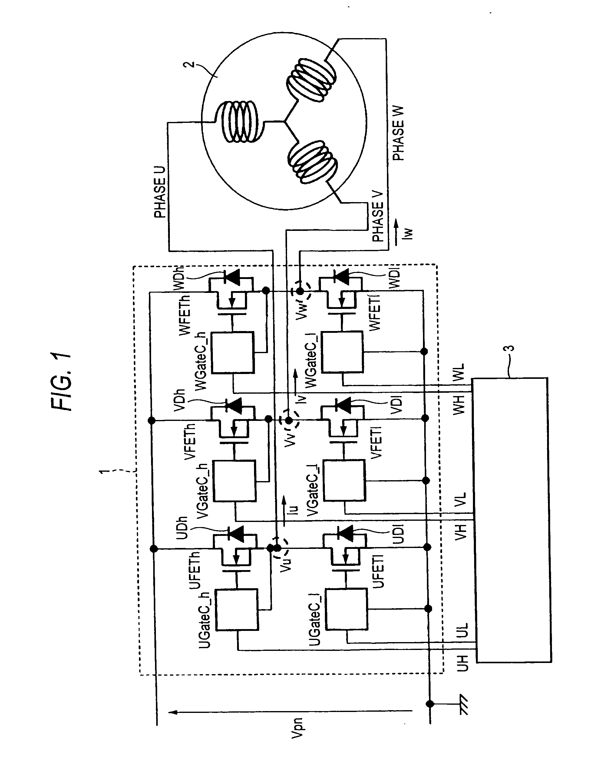
[0029]FIG. 1 shows the entire configuration of a power controlling apparatus according to Embodiment 1 of the invention. A three-phase power converting circuit 1 carries out a bidirectional power converting operation by a controlling circuit 3. Reference symbol Vpn denotes the DC voltage of a DC power source. The terminals are connected to an energy accumulation source such as a battery. A motor / generator 2, which is a power generation motor, shifts power from the energy accumulation source to the motor / generator 2 by carrying out an inverter operation of the power converting circuit 1, and the motor / generator 2 generates a rotational drive force to rotate axles, etc., (motor drive operation). Also, the motor / generator 2 is rotated by power given by the outside, wherein three-phase AC power is generated, and the generated AC power is rectified by the power converting circuit 1 and is charged into the energy accumulation source of a battery, etc.

(Power Generation Operation).

[0030]...

embodiment 2

[0053] In the preceding Embodiment 1, although a description was given of a circuit configuration in the case where the input of the driver circuit is HIGH ACTIVE (HIGH voltage, and HIGH voltage is supplied to the gate of the power MOSFET). In Embodiment 2, a description is given of a circuit configuration in the case where the input of the driver circuit is LOW ACTIVE (with LOW voltage, and HIGH voltage is supplied to the gate of the power MOSFET). FIG. 5 shows a high-potential side of U-phase. Even if the input to the driver circuit is LOW ACTIVE, it is a matter of course that the low-potential side and other phases have the same construction.

[0054] Connections of the comparators CP1 and CP2 and resistors R5, R6, R7, R10, R11, R12 and R13 are the same as those in Embodiment 1. Output terminals of the comparators CP1 and CP2 are connected to the gates of the power source Vcc and switch Sw103 via a resistor R101. The source of the switch Sw103 is connected to the GND, and the drain...

embodiment 3

[0058] In the above-described Embodiments 1 and 2, a description was given of that, in the continuity period of the diode, the ON period of the power MOSFET is a ratio of two-thirds the entire continuity period of the diode. If the ON-period is made longer, it is possible to suppress heat generation in the elements. In the present Embodiment 3, a description is given of a circuit configuration and actions for making the ON period longer.

[0059]FIG. 6 shows a construction of Embodiment 3, which shows a construction of only the U-phase high-potential side. The constructions at the low-potential side and in the other phases are the same. Connections of the comparators CP1 and CP2 and resistors R2, R5, R6, R7, R10, R11, R12, and R13, switch Sw1 and diode D1 are the same as those in Embodiment 1.

[0060] The output terminals of the comparators CP1 and CP2 are connected to the power Vcc via a resistor R201, and connected to one input terminal of the NOR circuit IC201 and the resistor R215....


PUM


Abstract

The invention provides an apparatus for bi-directional power conversion between a DC circuit and an AC circuit, which inexpensively and simply suppresses generation losses of elements and reduces heat generation, wherein a voltage obtained by dividing the U-phase voltage Vu is compared with a voltage obtained by dividing the voltage vpn of a DC circuit by a comparator CP1, and the MOSFET UFETh is turned on at the output timing thereof, and a voltage obtained by dividing the V-phase voltage Vv is compared with a voltage obtained by dividing the voltage Vpn of a DC circuit by a comparator CP2, and the MOSFET UFETh is turned off at the output timing thereof.

Description

BACKGROUND OF THE INVENTION [0001] 1. Field of the Invention [0002] The present invention relates to a power controlling apparatus provided with a power converting circuit for carrying out bi-directional power conversion between a DC circuit and an AC circuit, and particularly for attempting to lower the generation loss thereof. [0003] In a prior art power controlling apparatus for power conversion between a DC power source and a motor / generator, for example, in Patent Document 1, an overheated state of a diode is detected by a thermistor when operating for power generation, and the power generation is stopped when the overheated state is continued for a specified period of time. [0004] In order to lower a generation loss of a diode, for example, in Patent Document 2, there is a rectification device of an AC power generator, and a circuit in which a switching element is connected in parallel to the diode is disclosed. [0005] Patent Document 1 [0006] Japanese Published Unexamined Pat...

Claims


Application Information

Patent Timeline
IPC IPC(8): H02M7/219H02M7/48H02M7/797
CPCH02M7/797H02M7/219
Inventor URAKABE, TAKAHIROOKUDA, TATSUYAASAI, TAKAMASAGOTOU, SIGETADA
Owner MITSUBISHI ELECTRIC CORP
Why Eureka
Try Eureka