Process and device for coupling hollow fibers to a microfluidic network

a microfluidic network and hollow fiber technology, applied in the direction of fluid speed measurement, optical light guides, photomechanical treatment, etc., can solve the problems of inability to ensure the optimal positioning of hollow fibers in channels, inability to ensure the optimal positioning of hollow fibers, and inability to ensure the effect of hollow fiber positioning

Active Publication Date: 2005-05-19
BOEHRINGER INGELHEIM MICROPARTS
View PDF4 Cites 31 Cited by
  • Summary
  • Abstract
  • Description
  • Claims
  • Application Information

AI Technical Summary

Benefits of technology

[0011] A primary object of this invention is to devise a process for coupling at least one microfluidic hollow fiber to a microfluidic network and a microfluidic system provided with it, unwanted sealing of the hollow fiber by c

Problems solved by technology

This is difficult when several parts are to be fluidically tightly cemented to one another on different planes, especially when one of the components which is to be cemented to another is comparatively movable, especially for a hollow fiber.
However, the known process does not ensure optimum positioning of the hollow fiber in the channel.
The problem is especially that excess cement can undesirably penetrate in

Method used


Image

  • Process and device for coupling hollow fibers to a microfluidic network
  • Process and device for coupling hollow fibers to a microfluidic network
  • Process and device for coupling hollow fibers to a microfluidic network

Examples


Embodiment Construction

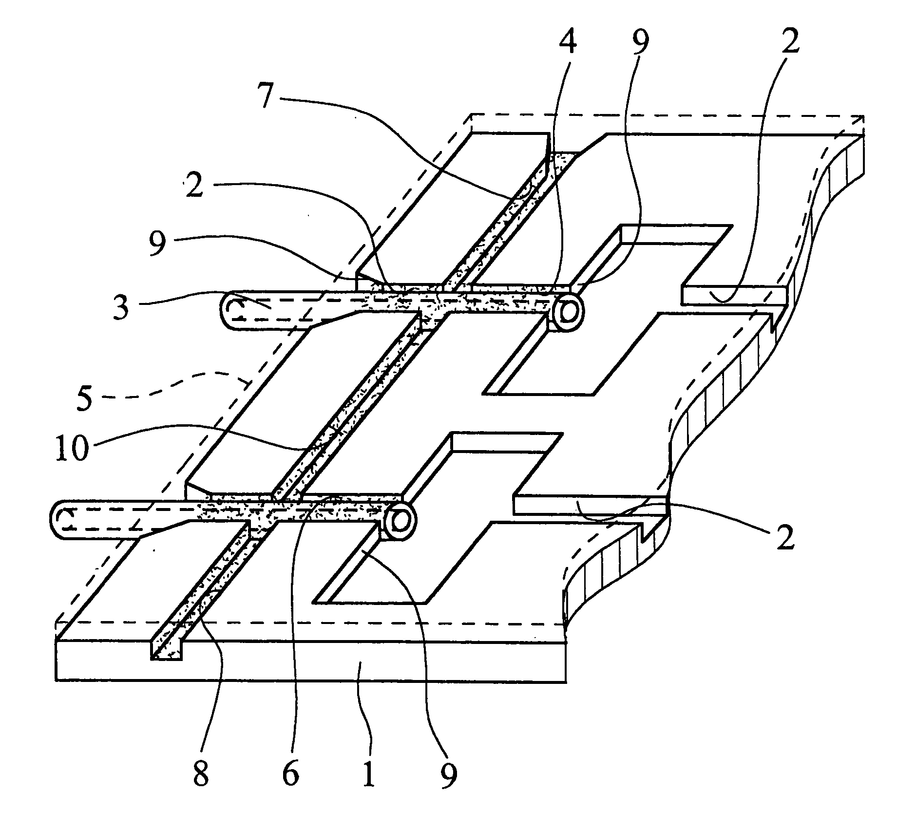
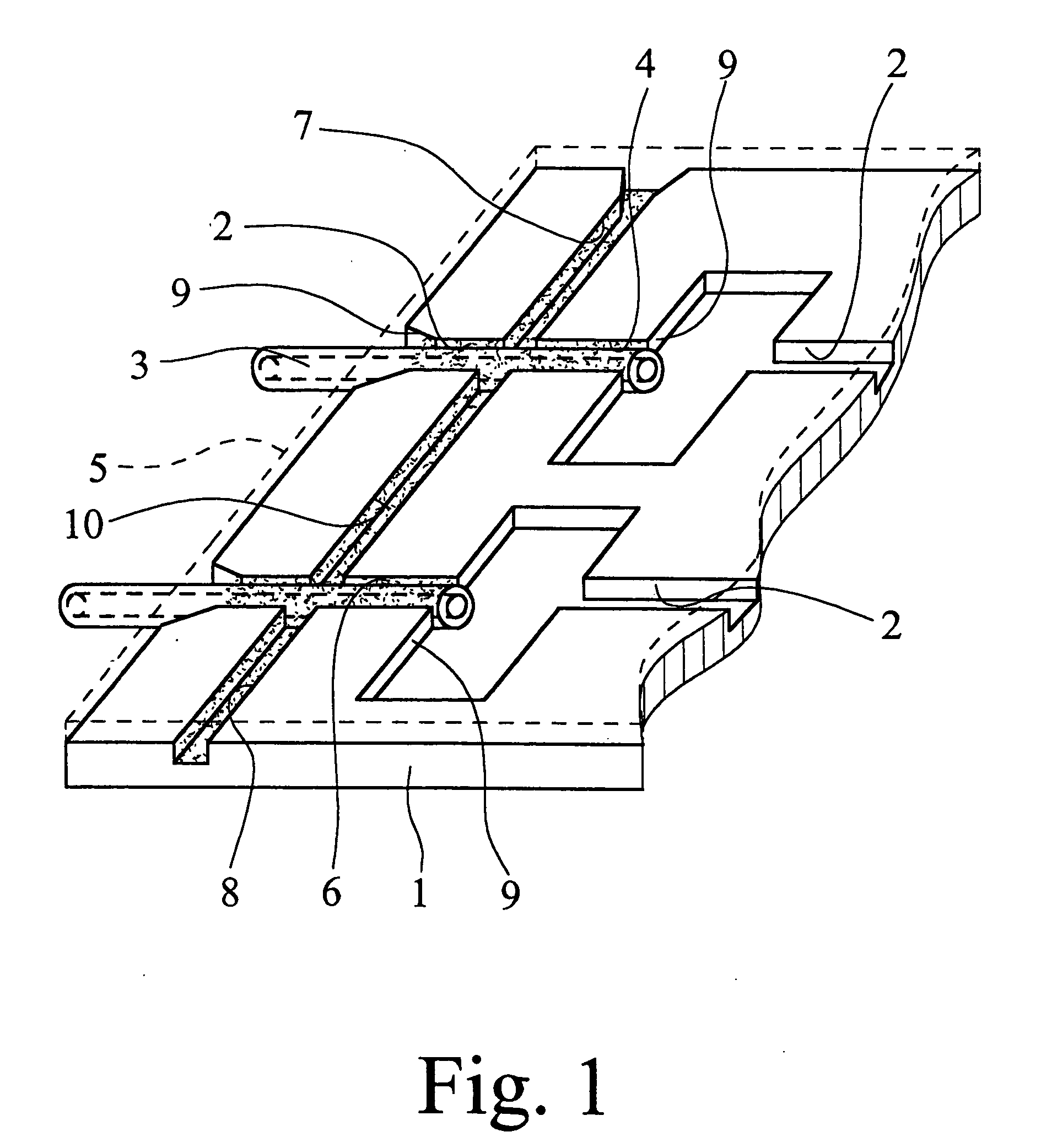
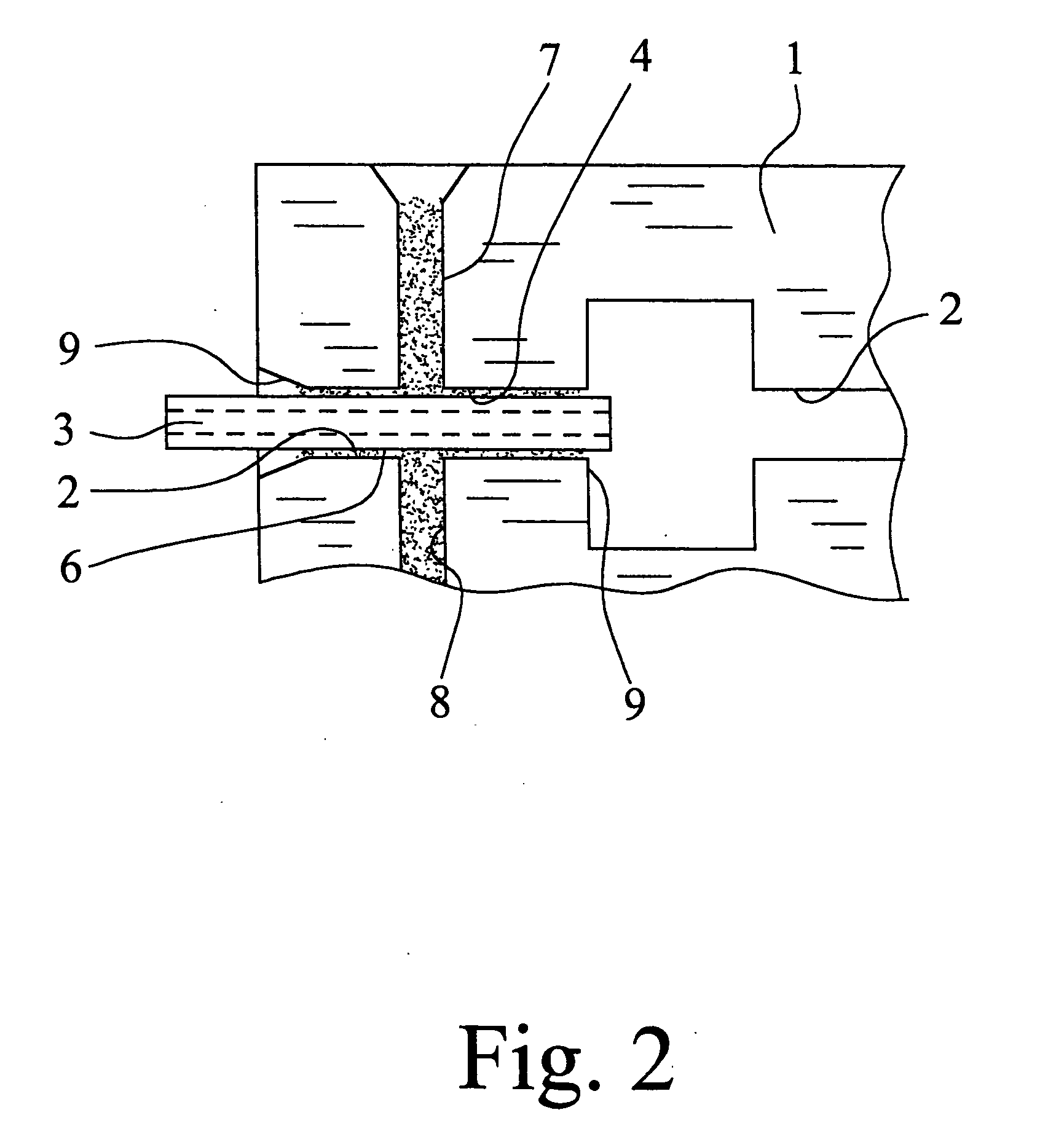
[0034] The microfluidic system which is shown in FIG. 1 is composed of a microfluidic network with a microstructure carrier 1 with at least one channel 2 and a microfluidic hollow fiber 3, one end of which is inserted into the channel 2 and which discharges at its end face into the channel 2. The outside dimensions, especially the outside diameter, of the hollow fiber 3 are matched to the inside dimensions, especially the width and the depth, of the channel 2, such that capillary channels 4 are formed between the hollow fiber 3 and the walls of the channel 2, especially in the gussets which remain in the angles. Additionally, the network is covered with a cover film or plate 5 which is fixed on the microstructure carrier 1 and which closes the channel 2. The capillary channels 4 are filled by a fluidically sealing cement 6. The cover film 5 is represented in FIG. 1 only by a broken line and not to scale, and is a hot sealing film of a polymer plastic, here, which is permeable to UV ...


PUM

PropertyMeasurementUnit
Widthaaaaaaaaaa
Widthaaaaaaaaaa
Widthaaaaaaaaaa

Abstract

A microfluidic network having at least one channel which is open on the top side and in which one end of at least one hollow fiber is inserted and a process for making it. For this it is provided that the outside dimensions of the hollow fiber are matched to the inside dimensions of the channel, capillary channels being formed between the hollow fiber and the walls of the channel. The network is covered with a cover film or plate which closes the channel and preferably fixes the hollow fiber temporarily in the channel, and the capillary channels are filled with a fluidically sealing cement. In the area of the inserted end of the hollow fiber, a capillary stop structure is formed so that the cement as it is added it cannot seal the inserted open end of the hollow fiber.

Description

BACKGROUND OF THE INVENTION [0001] 1. Field of the Invention [0002] The invention relates first of all to a process for coupling at least one hollow fiber to a microfluidic network, the microfluidic network having at least one channel which is open on the top side and in which the hollow fiber is inserted with one end. Furthermore the invention relates to a device for implementing this process, specifically a microfluidic system consisting of a microfluidic network with a microstructure carrier and a coupled microfluidic hollow fiber which is inserted with one end in the channel and which discharges on the face side into the channel. [0003] 2. Description of Related Art [0004] In Microsystems engineering, connecting components with microstructured surfaces to one another by cementing is known. With these processes, often only two planar parallel surfaces are cemented to one another. In doing so, cement flows in one plane. In order to cement to one another the components to be joined...

Claims


Application Information

Patent Timeline
IPC IPC(8): B01J19/00B01L3/00B81B1/00B81C3/00
CPCB01J19/0093B01J2219/00783B01J2219/00813B01L3/502707B01L3/502715Y10T436/25B01L2200/0689B81B2201/058B81C3/001B81C2203/032Y10T436/2575B01L2200/027
Inventor YU, YINGPETERS, RALF-PETERSTOETERS, WOLFGANG
Owner BOEHRINGER INGELHEIM MICROPARTS
Why Eureka
Try Eureka