Powered surgical apparatus, method of manufacturing powered surgical apparatus, and method of using powered surgical apparatus
Active Publication Date: 2005-05-19
GYRUS ACMI INC (D B A OLYMPUS SURGICAL TECH AMERICA)
View PDF56 Cites 419 Cited by
Summary
Abstract
Description
Claims
Application Information
AI Technical Summary
This helps you quickly interpret patents by identifying the three key elements:
Problems solved by technology
Method used
Benefits of technology
Benefits of technology
[0009] The invention addresses the above and / or other concerns and can provide a powered surgical apparatus, method of manufacturing the powered surgical apparatus, and method of using the powered surgical apparatus that facilitates ease of operation and / or promotes utility of operation. The invention can also provide apparatus and methods that facilitate and promote ease and effectiveness of cleaning and / or sterilization of at least a portion of the apparatus.
[0033] This cutting blade assembly provides various advantages. For example, the cutting blade assembly provides a structure that does not require the source of irrigation fluid to directly be connected to it, which enables the cutting blade assembly to be changed without requiring that the source of irrigation fluid be disconnected from the handle.
Problems solved by technology
However, the body of the handpiece of a surgical apparatus, such as the surgical shaver of the 527 patent, is typically more heavy than a common writing apparatus, such as a pencil or a pen.
Thus, the hand muscles of an operator, such as a surgeon, used to grasp the body of the handpiece of the surgical apparatus in this manner may tire during a surgical operation, which can take a considerable amount of time.
Also, the surgeon may find it difficult to rotate the colletassembly to move the cutting window of the outer blade while supporting the weight of the surgical apparatus by grasping the body of the handpiece as if it was a writing instrument.
Further, the surgeon may find the operation of gripping the body of the handpiece of the surgical apparatus as if it was a writing apparatus to be otherwise cumbersome, unnatural or troublesome.
Method used
Image
Click on the blue label to locate the original text in one second.
Reading with bidirectional positioning of images and text.
Examples
Embodiment Construction
[0077] For convenience of explanation, exemplary embodiments of the invention are described below with reference to the figures in the context of human surgery, such as ear, nose and throatsurgery, and in particular sinus surgery. However, as previously discussed, all exemplary embodiments of the invention are intended to be used in any applicable field of endeavor.
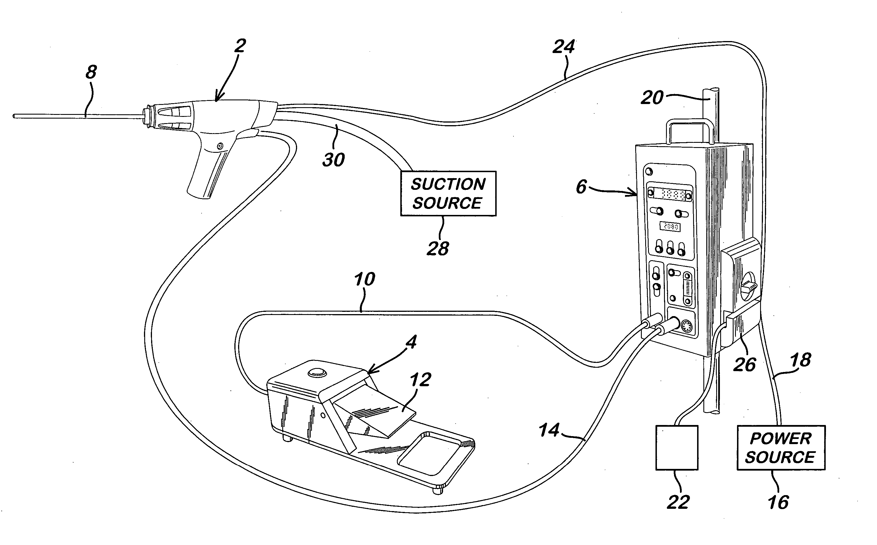
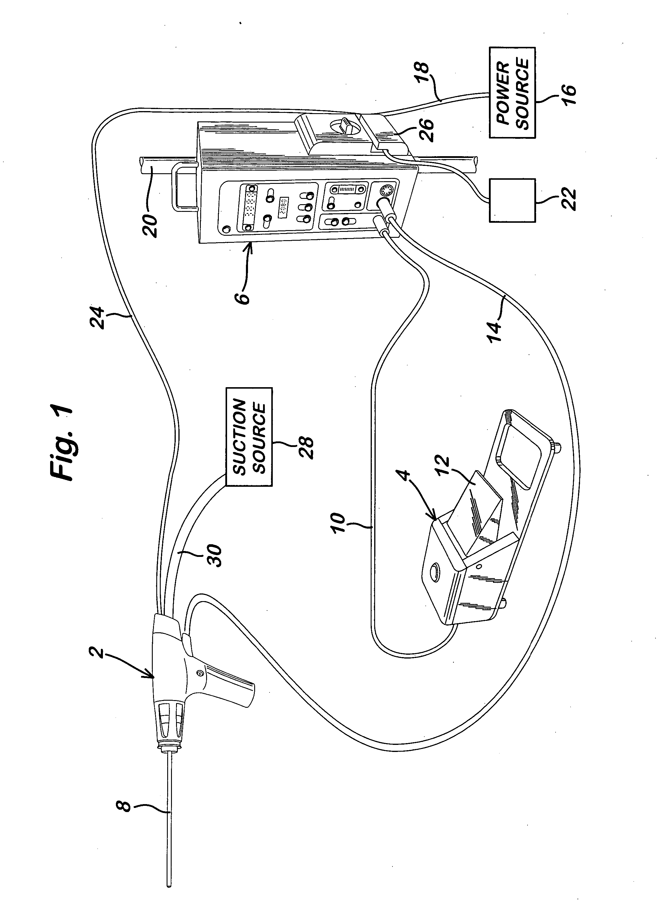
[0078]FIG. 1 is a schematic of a powered surgical apparatus 1 in accordance with an exemplary embodiment of the invention. As shown in FIG. 1, the apparatus 1 includes a handle 2, a footswitch 4 and a controller 6. A general description of these elements as well as their interrelationship is provided below.
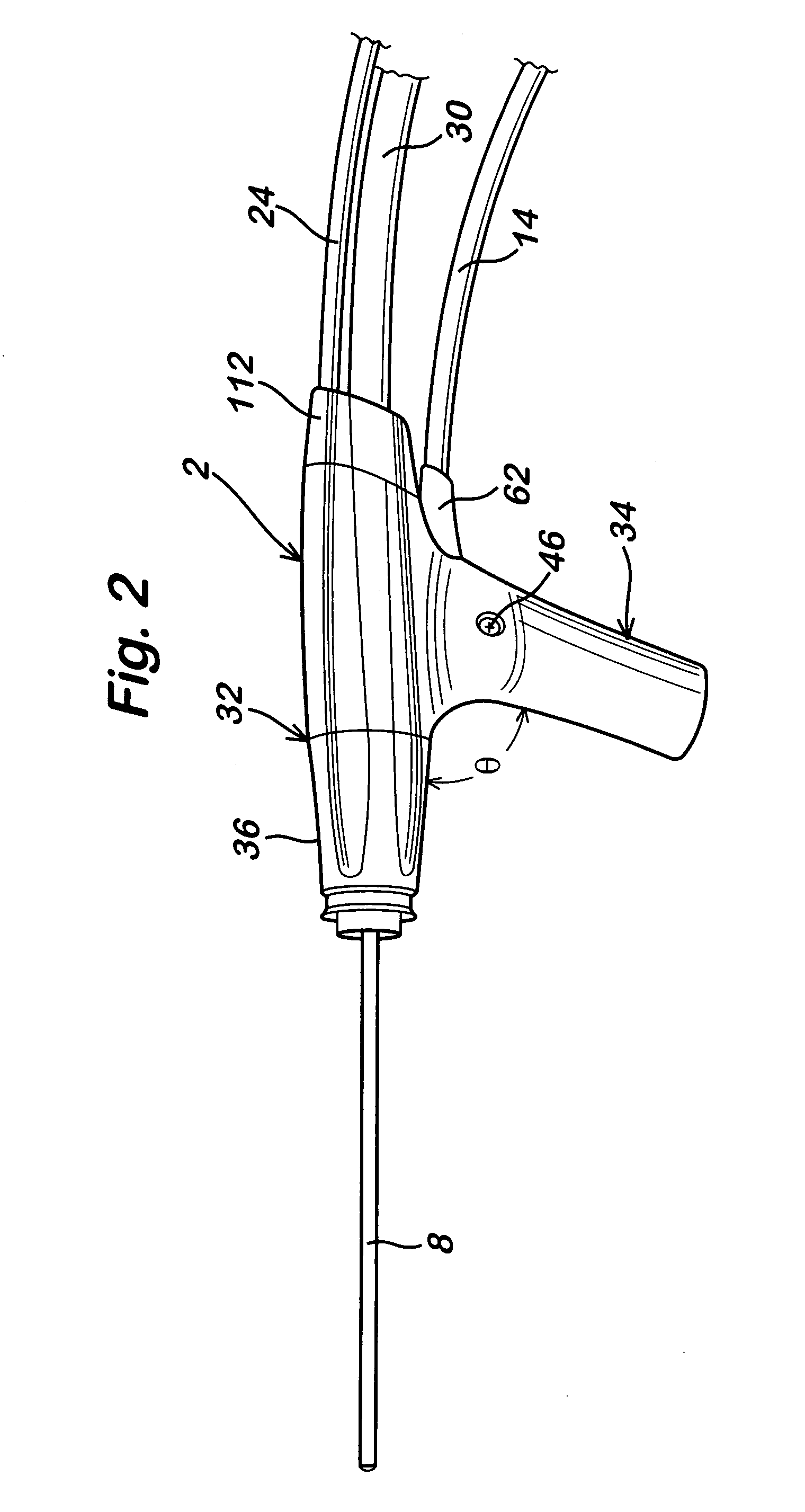
[0079] The handle 2 includes a cutting blade assembly 8 at its distal end. The distal end of the cutting blade assembly 8 is usable to cut, shave and / or remove bodily material during a surgical procedure or operation. The distal end of the cutting blade assembly 8 can perform the cuttin...
PUM
Abstract
A powered surgical apparatus can be used with a source of irrigation fluid and a source of suction. The powered surgical apparatus can include a cutting blade assembly and a handle. The handle can include an upper portion defining a distal section connectable to the cutting blade assembly and a lower portion extending downwardly from the upper portion. The handle can be connectable to the source of irrigation fluid and the source of suction. The system can also include a manually actuable input device that provides at least one signal relevant to at least one operation of the system, and a controller that receives the at least one input signal and provides an output signal to perform the at least one operation of the system.
Description
[0001] This is a Division of application Ser. No. 10 / 103,104 filed Mar. 22, 2002, which claims the benefit of U.S. Provisional Application No. 60 / 366,224 filed Mar. 22, 2002. The entire disclosure of the prior applications is hereby incorporated by reference herein in its entirety.BACKGROUND OF THE INVENTION [0002] 1. Field of Invention [0003] The invention relates to a powered surgical apparatus, a method of manufacturing the powered surgical apparatus, and a method of using the powered surgical apparatus. In particular, the invention relates to such a powered surgical apparatus usable to shave, cut and / or remove tissue, bone and / or any other bodily material. [0004] 2. Description of Related Art [0005] Surgical apparatus are powered to enhance shaving, cutting and / or removal of tissue, bone and / or other bodily material. Such powered surgical apparatus can include a shaving or cutting instrument, such as a rotating blade, for example. The rotating blade can be connected to a handpie...
Claims
Application Information
Patent Timeline
Application Date:The date an application was filed.
Publication Date:The date a patent or application was officially published.
First Publication Date:The earliest publication date of a patent with the same application number.
Issue Date:Publication date of the patent grant document.
PCT Entry Date:The Entry date of PCT National Phase.
Estimated Expiry Date:The statutory expiry date of a patent right according to the Patent Law, and it is the longest term of protection that the patent right can achieve without the termination of the patent right due to other reasons(Term extension factor has been taken into account ).
Invalid Date:Actual expiry date is based on effective date or publication date of legal transaction data of invalid patent.
InventorJOHNSTON, CONSTANCE ELAINERYAN, PHILLIP ANDREWMILLS, CARRIE DEANNEMYKLEBY, PERRY ROBINBURROUGHS, ANDREW CHRISTOPHERRUSH, BENJAMIN LEOKARAHALIOS, TASOS GEORGEBRAUER, JACOB SHIEFFELINMONSON, RODNEY HALSUGALSKI, ERIC CHRISTOPHERISAACS, DICKONTAPPEL, JAMES GERARDENDERS, THOMAS FRANZCHOW, BENJAMIN MARKCRUSE, ENERGY IIBRENNEMAN, SCOTT ANDREW
OwnerGYRUS ACMI INC (D B A OLYMPUS SURGICAL TECH AMERICA)

