Self-adjusting friction clutch

a friction clutch and self-adjusting technology, which is applied in the direction of friction clutches, interlocking clutches, clutches, etc., can solve the problems of affecting the operation of the adjusting device, and the adjusting device is no longer capable of carrying out the adjusting function. , to achieve the effect of simple and inexpensive manner

Inactive Publication Date: 2000-08-08
LUK LAMELLEN & KUPPLUNGSBAU BETEILIGUNGS KG
View PDF14 Cites 27 Cited by
  • Summary
  • Abstract
  • Description
  • Claims
  • Application Information

AI Technical Summary

Benefits of technology

An object of the present invention is to avoid the aforediscussed drawbacks and to provide a clutch assembly of the aforedescribed class wherein the adjusting device is capable of

Problems solved by technology

Clutch assemblies or friction clutches utilizing an integrated adjusting device which compensates at least for the wear upon the friction linings of the clutch disc exhibit the drawback that, especially when employing so-called mechanical disengaging systems wherein the movements of the clutch pedal are transmitted to the actuating means of the friction clutch by way of a linkage and/or a Bowden wire with the interposition of at least one disengaging bearing, due to tolerances within the entire kinematic train one cannot ensure that those portions of the disengaging member which act upon the actuating means invariably assume the same axial position relative to those portions of the actuating means which are to be acted upon.
This can result in relatively large departures of the disengagi

Method used


Image

  • Self-adjusting friction clutch
  • Self-adjusting friction clutch
  • Self-adjusting friction clutch

Examples


Embodiment Construction

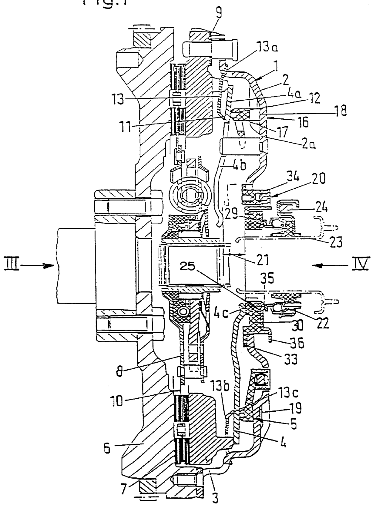
The clutch assembly which is shown in FIG. 1 comprises a friction clutch 1 with a housing 2 and a pressure plate 3 which is non-rotatably connected to but is movable axially within limits relative to the housing. A biasing diaphragm spring 4 is stressed between the pressure plate 3 and the cover 2 and is tiltable relative to a ring-shaped seat assembly 5 which is carried by the housing. The spring 4 acts upon the pressure plate 3 to urge the latter toward a counterpressure plate 6, for example a flywheel, whereby the friction linings 7 of the clutch disc 8 are clamped between the friction surfaces of the pressure plate 3 and the counterpressure plate 6.

The pressure plate 3 is non-rotatably connected with the housing 2 by circumferentially or tangentially oriented leaf springs 9. In the illustrated example, the clutch disc 8 comprises so-called springy friction lining segments which ensure a progressive buildup of torque during engagement of the friction clutch 1 by permitting a limi...


PUM


Abstract

A friction clutch wherein an adjusting device serves to compensate for wear at least upon the friction linings of the clutch disc between the driven counterpressure plate and the axially movable pressure plate. The purpose of the adjusting device is to ensure that the bias of the clutch spring upon the pressure plate remains at least substantially unchanged. The adjusting device satisfies such requirement due to the provision of a device which compensates for departures of the actual position of the clutch actuating unit from an optimum position or which compensates for the departures of those portions of the actuating unit relative to a clutch disengaging member from an optimum position which are acted upon by the actuating unit.

Description

The invention relates to a clutch assembly with a friction clutch comprising a pressure plate which is non-rotatably connectable with a counterpressure plate for limited axial movement with respect thereto, at least one biasing spring being provided to urge the pressure plate toward a clutch disc which can be clamped between the pressure plate and the counterpressure plate and there being further provided an adjusting device to compensate at least for the wear upon the friction linings of the clutch disc to effect a substantially unchanged application of force by the biasing spring to the pressure plate, the friction clutch further comprising actuating means for engaging and disengaging the clutch and the actuating means being operable by a disengaging member which is shiftable axially by a disengaging means, e.g., a disengaging fork which is pivotably mounted on a transmission case.A clutch assembly which is constructed and which is operable in the aforedescribed manner is known, f...

Claims


Application Information

Patent Timeline
IPC IPC(8): F16D13/58F16D13/75F16D13/71F16D23/14
CPCF16D13/755F16D2013/581F16D2013/706F16D13/757F16D2013/703F16D2300/18
Inventor KIMMIG, KARL-LUDWIGWITTMANN, CHRISTOPHREIK, WOLFGANGMAUCHER, PAULMEINHARD, ROLF
Owner LUK LAMELLEN & KUPPLUNGSBAU BETEILIGUNGS KG
Why Eureka
Try Eureka