Collision-prediction unit for a vehicle

a technology for vehicles and collisions, applied in scene recognition, pedestrian/occupant safety arrangement, instruments, etc., can solve problems such as limited versatility

Inactive Publication Date: 2005-05-19
DENSO CORP
View PDF11 Cites 69 Cited by
  • Summary
  • Abstract
  • Description
  • Claims
  • Application Information

AI Technical Summary

Problems solved by technology

The driving support system described above estimates the probability of a collision based on information

Method used


Image

  • Collision-prediction unit for a vehicle
  • Collision-prediction unit for a vehicle
  • Collision-prediction unit for a vehicle

Examples


first embodiment

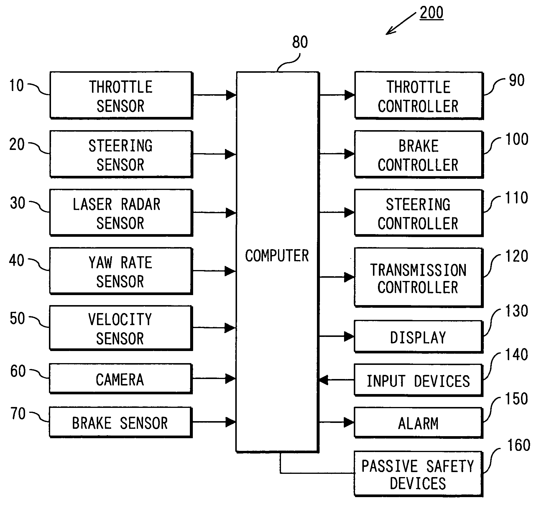
[0018]FIG. 1 depicts a driving support system 200 in accordance with the principles of the present invention. The driving support system 200 includes a throttle sensor 10, a steering sensor 20, a laser radar 30, a yaw rate sensor 40, a velocity sensor 50, a camera 60 with an imaging device such as a CCD (Charge-Coupled Device) or a CMOS (Complementary Metal Oxide Semiconductor) sensor, a brake sensor 70, a throttle controller 90, a brake controller 100, a steering controller 110, a transmission controller 120, a display 130, an input device 140, an alarm 150, and passive safety devices 160.

[0019] The driving support system 200 further includes a computer 80 in data communication with each of the components listed above. The computer 80 includes input / output interfaces and an assortment of electrical control circuits as is commonly known in the industry.

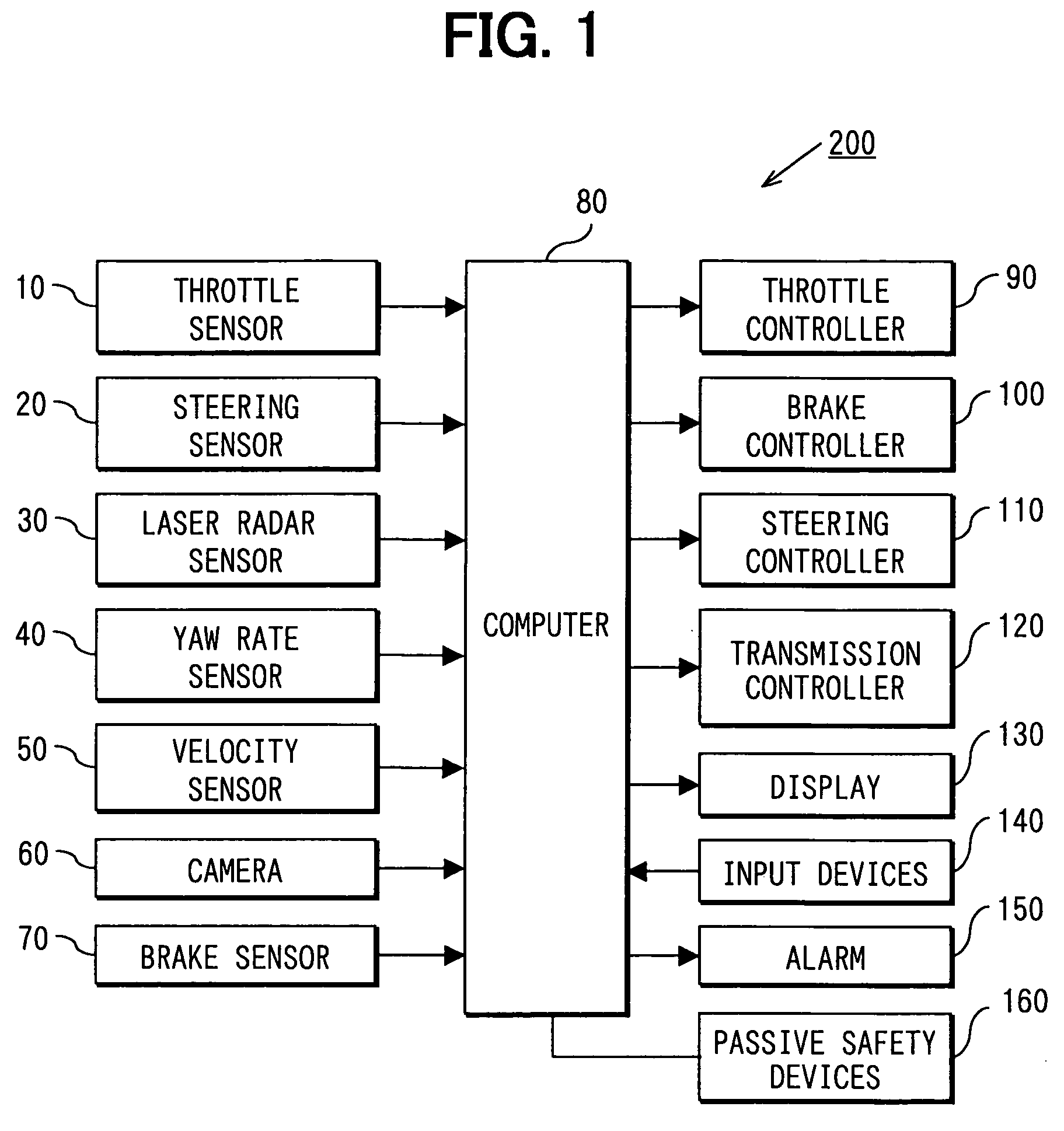
[0020] In general, the computer 80 is adapted to estimate a probability that the vehicle equipped with the driving support system ...

second embodiment

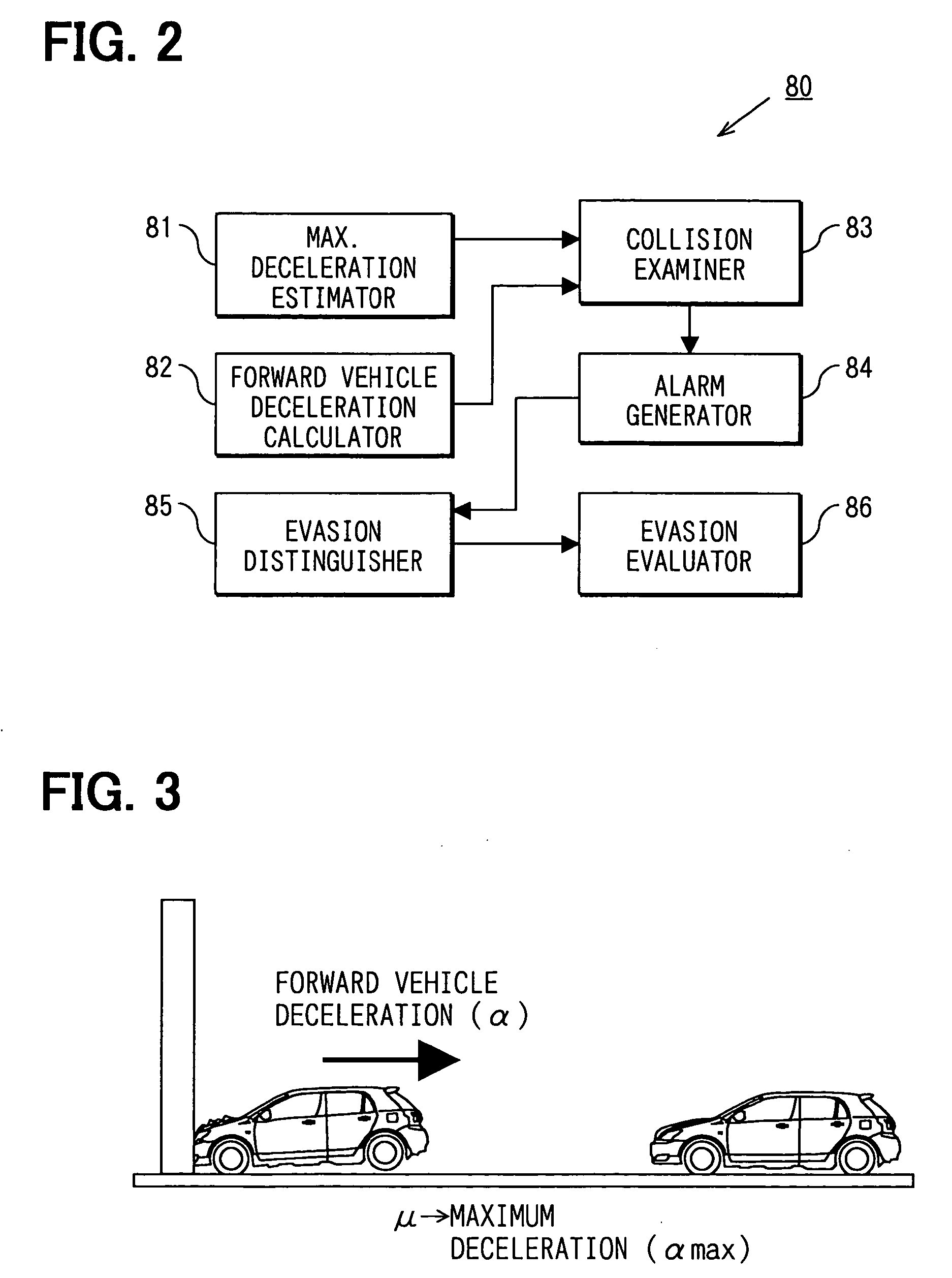
[0054] The second embodiment is described focusing on its differences from the first embodiment. The first embodiment identifies the imminence of a collision by comparing the forward vehicle deceleration (α) to the maximum deceleration (αmax), as described above. The driving support system 200 of the second embodiment identifies the imminence of a collision by comparing a vehicle velocity to a relative vehicle velocity defined as the difference between the velocities of the vehicle and the forward vehicle.

[0055]FIG. 5 is a block diagram showing the computer 80 of the second embodiment including a driving state retriever 81a, a collision examiner 83a, an alarm generator 84, an evasion distinguisher 85, and an evasion evaluator 86. The alarm generator 84, evasion distinguisher 85, and evasion evaluator 86 in FIG. 5 execute the same processes as described above in accordance with the first embodiment and, therefore, are identified by like reference characters.

[0056] The driving state...

modified embodiment 1

[0064] Furthermore, it should be appreciated that the alarm generator 84 of the first and second embodiments generates an alarm on the display 130 and / or the alarming device 150 to inform the driver that a collision is imminent. It should be appreciated that the alarm generator 84 may also include other alarming means such as honking the vehicle's horn, flashing the vehicle's headlights, or flashing the vehicle's hazard lights.


PUM


Abstract

A collision-prediction unit for a vehicle including a road condition detector, a maximum deceleration estimator, a forward vehicle detector, a forward vehicle deceleration calculator, and a collision examiner is provided. The road surface detector detects a condition of a road surface on which the vehicle travels. The maximum deceleration estimator calculates a maximum vehicle deceleration for the vehicle on the road surface having the detected condition. The forward vehicle detector detects a moving condition of a forward vehicle located ahead of the vehicle. The forward vehicle deceleration calculator calculates a forward vehicle deceleration based on the moving condition of the forward vehicle. The collision examiner determines whether a collision between the vehicle and the forward vehicle is imminent by comparing the forward vehicle deceleration to the maximum vehicle deceleration of the vehicle.

Description

CROSS REFERENCE TO RELATED APPLICATIONS [0001] This application is based upon and claims the benefit of priority of Japanese Patent Application No. 2003-384139, filed on Nov. 13, 2003, the contents of which are incorporated herein by reference. FIELD OF THE INVENTION [0002] The present invention relates to a collision-prediction unit for aiding in the prevention of vehicle collisions. BACKGROUND OF THE INVENTION [0003] JP2002-342899A discloses a driving support system for detecting the imminence of a vehicle colliding with another vehicle. The driving support system detects information including vehicle position, orientation, and velocity of a driven vehicle. The system retrieves object information including position, orientation, and velocity from a communication device located on at least one other vehicle. [0004] Based on the driving information and object information, the driving support system estimates a probability that a vehicle collision will occur. If the probability is hi...

Claims


Application Information

Patent Timeline
IPC IPC(8): B60R21/01B60R21/00B60R21/0134B60R21/16B60R22/46B60T7/12B60T7/22G08G1/16
CPCB60R21/0134G06K9/00805B60W10/06B60W10/10B60W10/18B60W10/20B60W30/08B60W30/09B60W2510/0604B60W2510/20B60W2520/10B60W2520/14B60W2550/20G08G1/16B60T7/22G08G1/166G08G1/167B60W2554/00B60W2540/18B60W2050/143G06V20/58
Inventor ISAJI, KAZUYOSHITSURU, NAOHIKO
Owner DENSO CORP
Why Eureka
Try Eureka