Collapsible liquid level measurement device with attachments

a liquid level measurement and collapsible technology, applied in liquid/fluent solid measurement, instruments, machines/engines, etc., can solve the problems of not meeting the current stringent accountability requirements, less than satisfactory accuracy, durability or dependability, and wooden gauge dipsticks

Inactive Publication Date: 2005-05-26
FLING WILLIAM F +1
View PDF3 Cites 11 Cited by
  • Summary
  • Abstract
  • Description
  • Claims
  • Application Information

AI Technical Summary

Benefits of technology

[0008] The present invention relates to a telescopic mechanized device for the measurement of fluid products contained in below-ground and above-ground tanks and containers. An attachment is provided for measuring the amount of water in the tanks or containers. A handle member forming the upper portion of the device within which an enclosed tubular housing having a plurality of openings in it side walls providing ready fluid communication from the out side to the tubular central space. A control bar extends along the inner cavity of the tubular housing and is pivotally mounted to swing from a first position extending laterally along a diameter of the housing to a second position closely adjacent to the housing interior wall. A float of outer diameter less t

Problems solved by technology

Wooden gauge dipsticks suffer from many deficiencies that make them less than satisfactory for accuracy, durability or dependability.
They do not meet current stringent requirements for accountability for tank leakage and product inventory control.
For example, scales are neither precise nor protected and thus are subject to wear and tear with repeated use.
The unprotected blunt end of the wood sticks damage the bottom of the tanks through pinning action and cause eventual erosion of the tank bottoms.
Wood sticks a

Method used


Image

  • Collapsible liquid level measurement device with attachments
  • Collapsible liquid level measurement device with attachments
  • Collapsible liquid level measurement device with attachments

Examples


Embodiment Construction

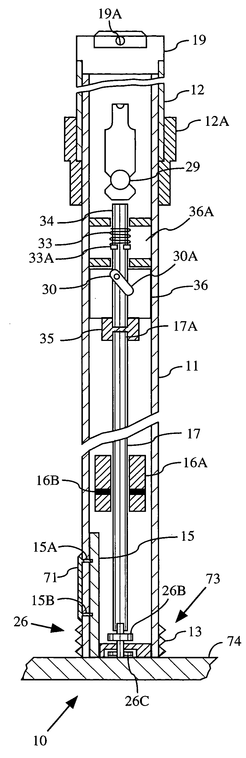
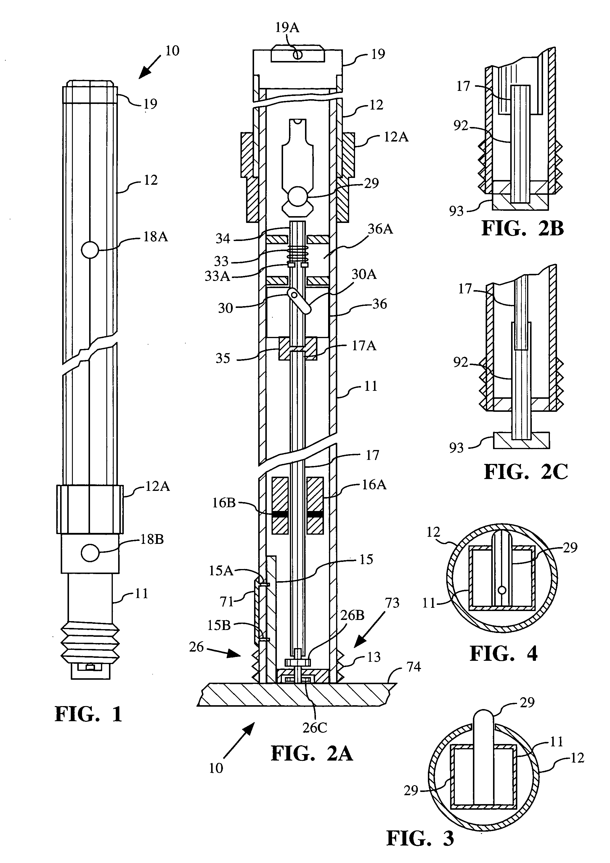
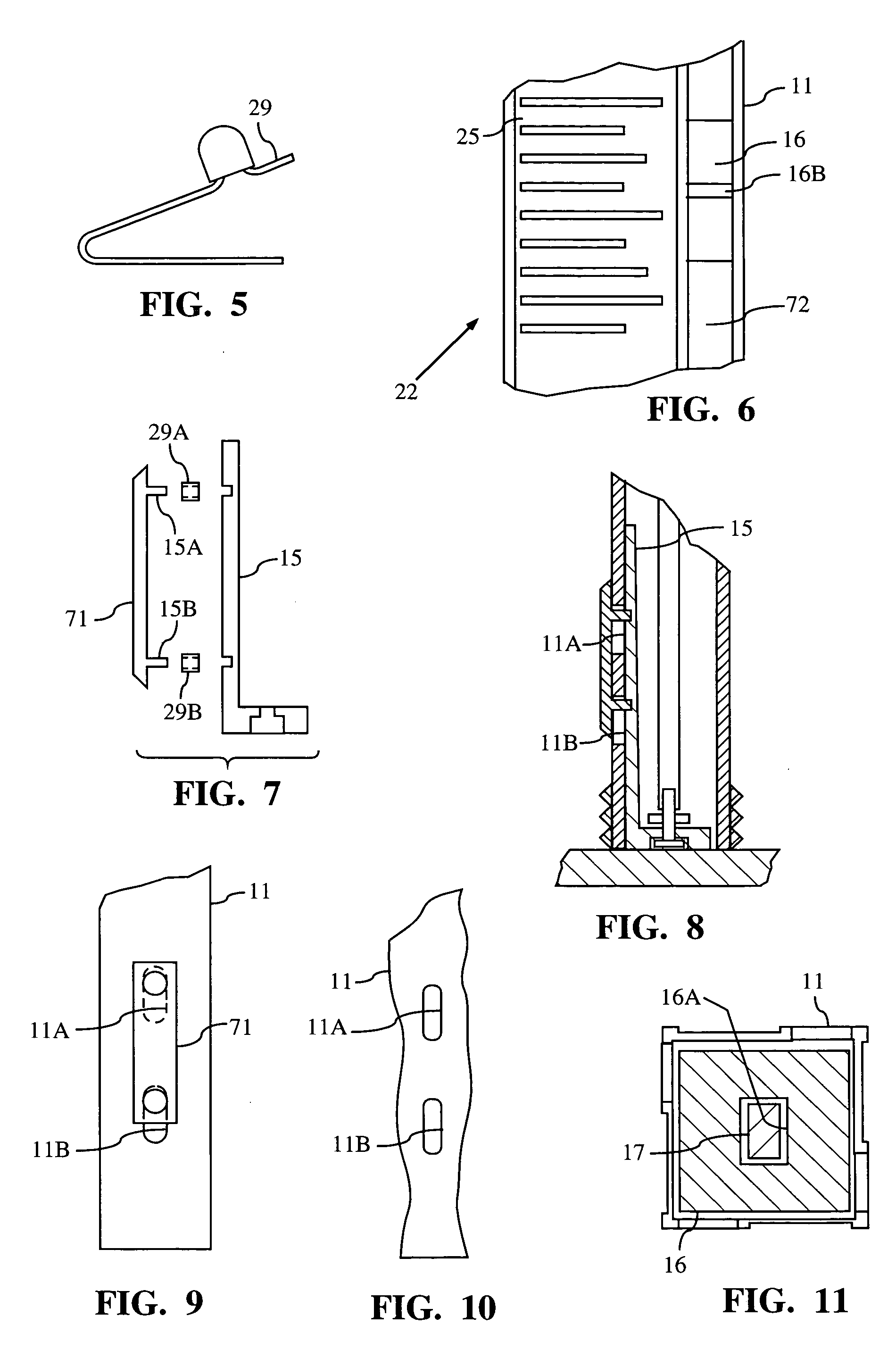
[0033] Turning now to the drawings and particularly to FIGS. 1, 2 and 3, a liquid level measuring device 10 includes an elongated tubular handle 12 and an elongated frame section 11. The handle 12 and the frame section 11 are connected in a telescopic relationship with the frame section 11 extending inside the handle 12 to form a rigid assembly that may be arranged in either an extended configuration for usage or a collapsed configuration for use in measuring liquid levels. It is a primary aim of the device described herein to measure the level of fluids in tanks or containers so that the fluid volume can be determined.

[0034] The liquid level measuring device 10 according to the invention may be advantageously employed for measuring fluids of great variety in containers and tanks such as, for example, containers for domestic heating oil, industrial fluid storage tanks, military storage facilities, gasoline stations, and the like. It is also considered within the spirit of this inve...


PUM


Abstract

A liquid level measuring device includes an elongate handle and an elongate frame arranged in telescoping relationship. The frame is movable between a collapsed position for storage and an extended position for usage. A float is movable lengthwise along the elongate frame. A control rod extends lengthwise in the elongate frame and through a passage in the float. The control rod controls movement of the float relative to the elongate frame. An actuator actuates the control arm to move the float from the locked position to the unlocked position in response to a downward pressure between a lower end of the elongate frame and a bottom surface of the container so that the float is free to seek the liquid level in the container and to move the float from the unlocked position back to the locked position when the downward pressure is released.

Description

CROSS REFERENCE TO RELATED APPLICATION [0001] Applicants claim priority for this application based upon U.S. Provisional Application No. 60 / 510,044.BACKGROUND OF THE INVENTION [0002] 1. Field of the Invention [0003] The present invention relates generally to the measurement of the depth of a quantity of liquid in a tank, container or the like, and, more particularly, to an improved liquid depth measurement device having a water level indicator and a fluid sampling device. [0004] 2. Description of the Prior Art [0005] There are many instances in which it is desirable or essential to be able to measure the depth of a fluid in large under ground and above ground storage tanks, container, or the like to determine the volume of the fluid contained therein. Large underground or above-ground bulk storage tanks are typically situated at gasoline service stations, convenience stores, factories, office buildings, truck stops, etc. In addition, the same requirements apply to numerous smaller t...

Claims


Application Information

Patent Timeline
IPC IPC(8): G01F23/30G01F23/64
CPCG01F23/0046G01F23/04G01N1/12G01F23/64G01F23/66G01F23/30
Inventor FLING, WILLIAM F.FLING, JOHN J.
Owner FLING WILLIAM F
Why Eureka
Try Eureka