
Systems and methods for the rapid deployment of piping

a technology of piping and rapid deployment, applied in the direction of loading/unloading vehicles, special-purpose vessels, transportation items, etc., can solve the problems of saving a large amount of time and effort, and achieve the effects of improving laying speed, rapid laying of piping, and enhancing the speed of laying pip

Active Publication Date: 2005-05-26
DRS SUSTAINMENT SYST
View PDF10 Cites 15 Cited by
  • Summary
  • Abstract
  • Description
  • Claims
  • Application Information

AI Technical Summary

Benefits of technology

[0020] Because of these and other problems in the art, described herein are systems and methods for allowing the rapid laying of piping from a deployment vehicle. The systems and methods utilize two structures to enhance the speed of laying pipe. Firstly, the systems and methods utilize spooled piping to allow for a longer single section of piping to be included on a deployment vehicle. Secondly, the entire piping operation utilizes smooth laying techniques and / or positioning systems designed to lay directly from the deployment vehicle to allow for improved laying of any individual section and for almost simultaneous laying (what is referred to herein as staggered laying) of multiple sections of piping.
[0021] This system can have numerous advantages over the systems of the prior art. In particular, the system can allow a significantly greater amount of piping to be stored in a single container and loaded on a single deployment vehicle than was available with systems which utilize rigid subsections. Further, the system can be designed to unspool the piping automatically or by a human operator working in conjunction with the movement of the vehicle. In this way, the laying operation can be performed by a vehicle supported by a few operators instead of a work team. Still further, a deployment vehicle can include a single continuous section of piping which is dramatically longer than any single piece of rigid piping which can be carried by the same vehicle eliminating many of the connection operations which in turn also decrease the number of persons needed to carry out the installation.
[0022] The systems and methods herein can also be designed to allow for a computation (a plot) of an entire pipeline lay including piping from multiple deployment vehicles prior to the laying of any piping. This computation can then allow for the dispatch of multiple deployment vehicles which will work in a staggered lay allowing the laying of an extended length of piping to be dramatically faster. In this way, a large series of pipe sections can be laid down at close to the same time, and be connected once all or almost all sections have been laid, saving a large amount of time and effort.
[0027] In an embodiment, there is described herein, a piping transport structure comprising: support means for providing a frame for the piping transport structure; reel means attached to the support means, the reel means having piping rolled thereon; outrigger means connected to the support means, the outrigger means allowing piping being unrolled from the reel means to be placed at a distance from the support means; and piping deployment means connected to the support structure, the piping deployment means controlling the speed the piping is unrolled from the reel means. In an embodiment, the piping deployment means also controls the speed that the piping is rolled onto the reel means.

Problems solved by technology

In this way, a large series of pipe sections can be laid down at close to the same time, and be connected once all or almost all sections have been laid, saving a large amount of time and effort.

Method used


Image

  • Systems and methods for the rapid deployment of piping
  • Systems and methods for the rapid deployment of piping
  • Systems and methods for the rapid deployment of piping

Examples


Embodiment Construction

)

[0037] In order to effectively describe systems and methods for the laying of piping, this disclosure will begin by describing an embodiment of a piping transport structure and deployment vehicle and then go into how such a deployment vehicle can perform pipe laying of a single section. This disclosure will then turn to how a team of vehicles carrying similar piping transport structures can efficiently lay pipe by performing what is termed a staggered lay.

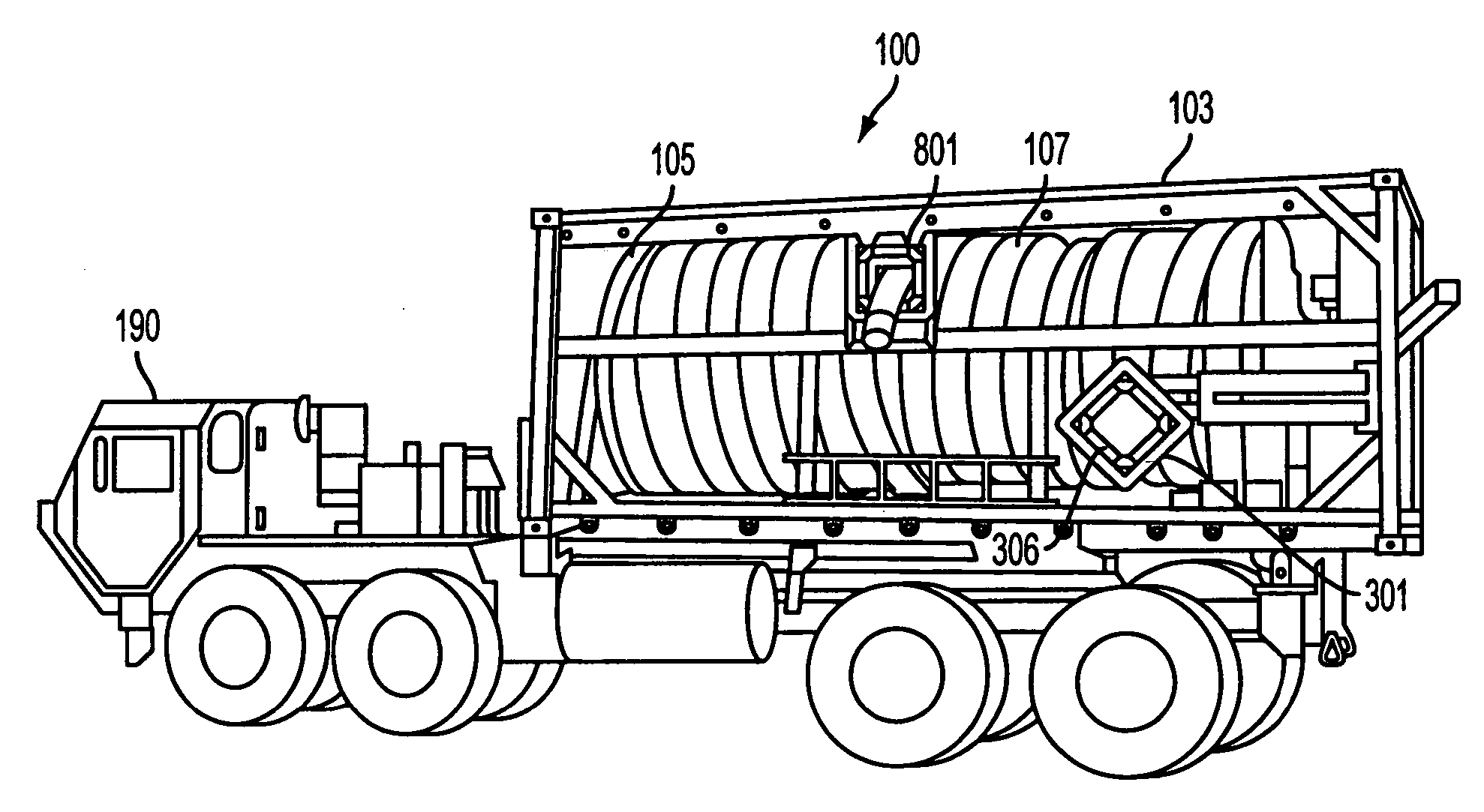
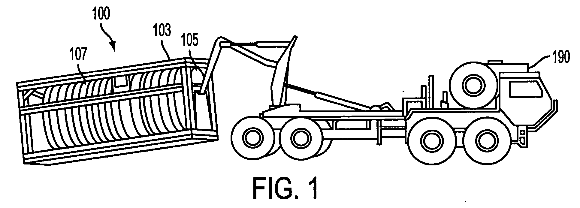
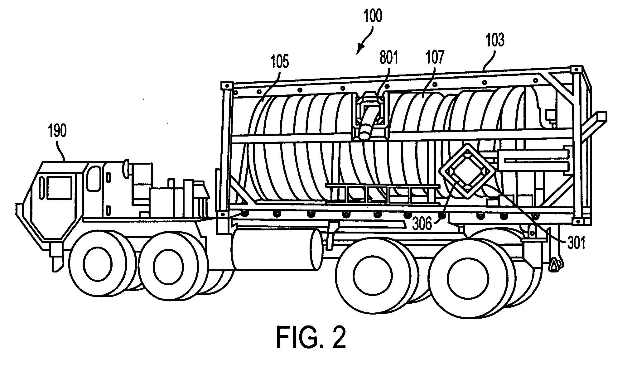
[0038]FIG. 1 shows an embodiment of a piping transport structure (100) being loaded on the back of a deployment vehicle (190) and comprising an embodiment of the invention. The piping transport structure (100) comprises three principle components. A support structure (103) which is generally of metal or other sturdy and strong material designed to support the weight of the other structures and to provide a shape and lift location for loading the piping transport structure (100) on the deployment vehicle (190). In a preferred embo...


PUM


Abstract

A piping transport structure for use with a deployment vehicle to provide for improved efficiencies in laying temporary or semi-permanent piping structures. There is also a system for having one or more deployment vehicles smoothly lay piping and to allow for long pipe lays to be carried out in less time.

Description

CROSS REFERENCE TO RELATED APPLICATION(S) [0001] This application claims priority to U.S. Provisional Application Ser. No. 60 / 486,486 filed Jul. 11, 2003, the entire disclosure of which is herein incorporated by reference. BACKGROUND OF THE INVENTION [0002] (1) Field of the Invention [0003] The present invention pertains to a truck-mounted pipe deployment system and methods for using a truck-mounted pipe deployment system to rapidly install temporary or semi-permanent piping lays with minimal labor requirements. [0004] (2) Background of the Invention [0005] Modern militaries consume a tremendous amount of fluid in their day-to-day activities. A modern fighting vehicle can bum through tens if not hundreds of gallons of fuel a day. Further, infantry and other human elements as well as vehicles require a large amount of water for drinking, cooking, cooling and other activities. This can add up to over 1 million gallons of fuel and water a day having to be provided at the military front...

Claims


Application Information

Patent Timeline
Patent Type & Authority Applications(United States)
IPC IPC(8): B60P1/64B60P3/00B65H49/20B65H75/34B65H75/40B65H75/44
CPCB60P1/6463B60P3/00B65H2701/33B65H75/4402B65H75/425
Inventor KRISE, MARTINBROUSSARD, KENWOOTTON, JOHN
Owner DRS SUSTAINMENT SYST
Learn More