Apparatus and method for contact-less switching

a technology of contact-less switching and apparatus, which is applied in the direction of instruments, point operation from vehicles, transportation and packaging, etc., can solve the problems of inability to operate the switch, inability to detect the movement of the switch, and ice accumulation, etc., to achieve economic feasibility and commercial practicability, and facilitate the effect of implementation

Active Publication Date: 2005-05-26
PROGRESS RAIL SERVICES
View PDF12 Cites 7 Cited by
  • Summary
  • Abstract
  • Description
  • Claims
  • Application Information

AI Technical Summary

Benefits of technology

[0007] The invention meets the above needs and overcomes one or more deficiencies in the prior art by providing an improved apparatus and method for detecting a position of a switching mechanism used to indicate a position of an object having a first position and a second position. In one embodiment, the invention uses existing components of the switching mechanism to vary the location of a magnet relative to a magnetically variable inductor to detect a position of the object. Moreover, the invention uses existing conductors connected to the switching mechanism to transmit a signal indicative of the position of the object to a remote location. By using the existing switching mechanism only the magnetically variable inductor and magnet are exposed to the harsh environment of the track location, and the existing wires connecting the existing contact switching mechanism 126 can be used to transmit the signal to a position detection circuit located within a shelter such as a signal house. The features of the present invention described herein are more efficient and easier to implement than currently available techniques as well as being economically feasible and commercially practical.

Problems solved by technology

Because it relies upon moving parts, it requires considerable maintenance (e.g., lubrication and adjustment).
In colder climates, ice may accumulate in or on such switching mechanisms and inhibit operation of the switch.
In addition, moisture and exposure can cause corrosion of one or more of the moving parts, which can result in unreliable operation of the switch.
However, such switching mechanisms are configured with three-conductor (i.e., wires) for connection to a circuit, and, thus, cannot be used with an existing switching mechanism configured for connection to a two-wire circuit.

Method used


Image

  • Apparatus and method for contact-less switching
  • Apparatus and method for contact-less switching
  • Apparatus and method for contact-less switching

Examples


Embodiment Construction

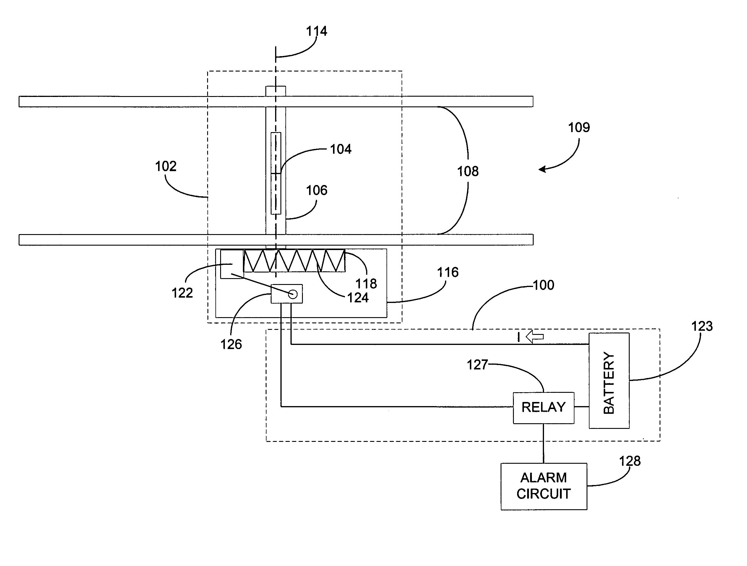
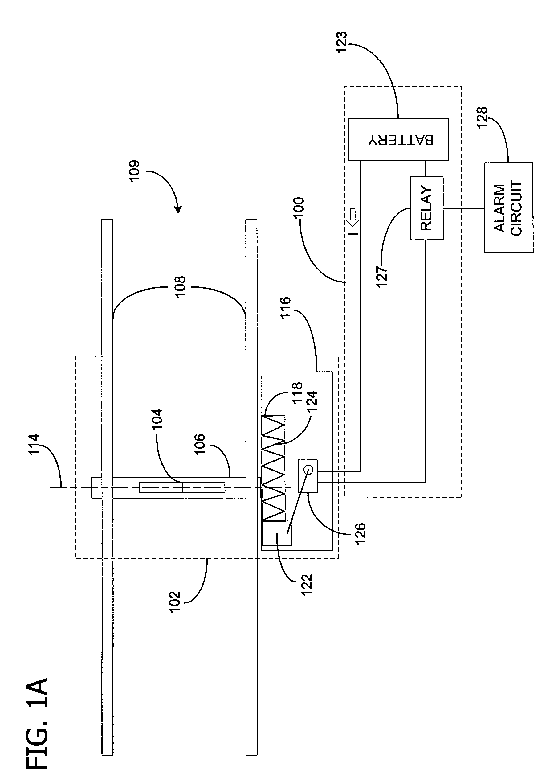
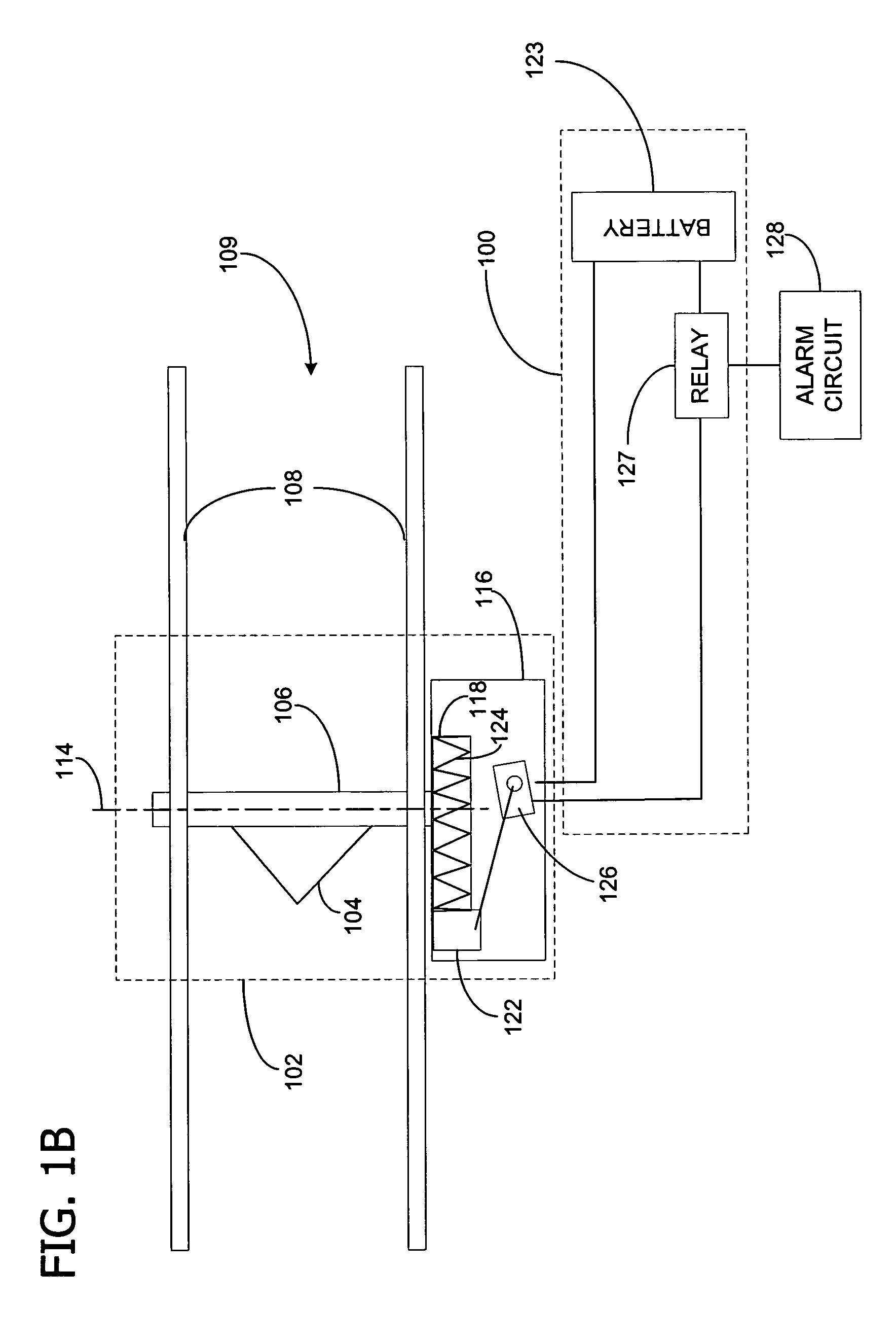
[0025] Railway dragging equipment detection systems provide notice of improperly connected equipment such as pneumatic braking lines by detecting hanging or dragging train loads or equipment and activating alarms to notify the appropriate personnel.

[0026] Referring now to FIGS. 1A and 1B, an existing switching circuit, indicated generally at 100, is shown for use with a DED system, indicated generally at 102. The switching circuit 100 includes a battery 123 for energizing a detector 127 (e.g., relay coil) connected in series with the battery. The DED system 102 includes an impact element 104, or paddle, fixedly mounted to a shaft 106. The shaft 106 extends between a pair of rails 108 of a railroad track 109, and is aligned such that it is generally perpendicular to the rails 108. The impact element 104 is positioned substantially vertical and upward (See FIG. 1A) such that it impacts an object suspended or hanging down from a train traveling along the track 109 when the train and o...


PUM


Abstract

An apparatus and method for use with a railroad dragging equipment detecting (DED) system that detects objects hanging from and dragged beneath a train as the train travels along rails of a railroad track. A generator supplies a first signal and is coupled to a magnetic amplifier coil to form a magnetically variable impedance circuit. The magnetic amplifier coil is responsive to the first signal to create a circuit impedance in series with a detection circuit. A magnet is mechanically connected to the cam/follower system and is positioned near the magnetic amplifier core for varying a circuit impedance of the detection circuit. A detection circuit generates a second signal as a function of variations in circuit impedance. A controller is responsive to the second signal for activating an alarm when the magnet moves relative to the magnetic amplifier coil.

Description

FIELD OF THE INVENTION [0001] The invention relates generally to railway dragging equipment detection (DED) systems. More particularly, the invention relates to an improved switching apparatus for activating an alarm when the DED system detects objects or equipment dragging beneath a train. BACKGROUND OF THE INVENTION [0002] To reduce the risk of derailment and other potential damage caused by dragging objects, DED systems or “draggers” have been used to detect the presence of objects dragging beneath a moving train. As an example, draggers may be placed at twenty (20) mile intervals over long stretches of a railroad track, in conjunction with other defect detection equipment. If a dragging object is detected, the train is stopped so that the object can be secured to reduce the potential for derailment or other problems. The height of the dragger is determined by balancing the risk of not detecting an object (such as an air hose), which is not dragging very far below the bottom of t...

Claims


Application Information

Patent Timeline
Patent Type & Authority Applications(United States)
IPC IPC(8): B61L23/00B61L23/04G01B7/30
CPCB61L23/041
Inventor BALLINGER, FORREST HENRY
Owner PROGRESS RAIL SERVICES
Why Eureka
Try Eureka