Charge pump with reduced noise

a technology of noise reduction and discharge pump, which is applied in the direction of dc-dc conversion, power conversion system, climate sustainability, etc., can solve the problems of excessive input and output ripple, noise affecting the operation of other circuitry, electrical noise,

Inactive Publication Date: 2005-05-26
SYNQOR
View PDF1 Cites 77 Cited by
  • Summary
  • Abstract
  • Description
  • Claims
  • Application Information

AI Technical Summary

Problems solved by technology

The operation of a charge pump, such as that in the ISL6526 controller, can produce electrical noise.
This noise affects the operation of other circuitry both within the controller IC and nearby on the PCB.
Artifacts of this noise can cause the power MOSFET switching times to be affected, resulting in excessive input and output ripple, acoustic noise, or other objectionable or erratic behavior.

Method used


Image

  • Charge pump with reduced noise
  • Charge pump with reduced noise
  • Charge pump with reduced noise

Examples


Embodiment Construction

[0023] A description of preferred embodiments of the invention follows.

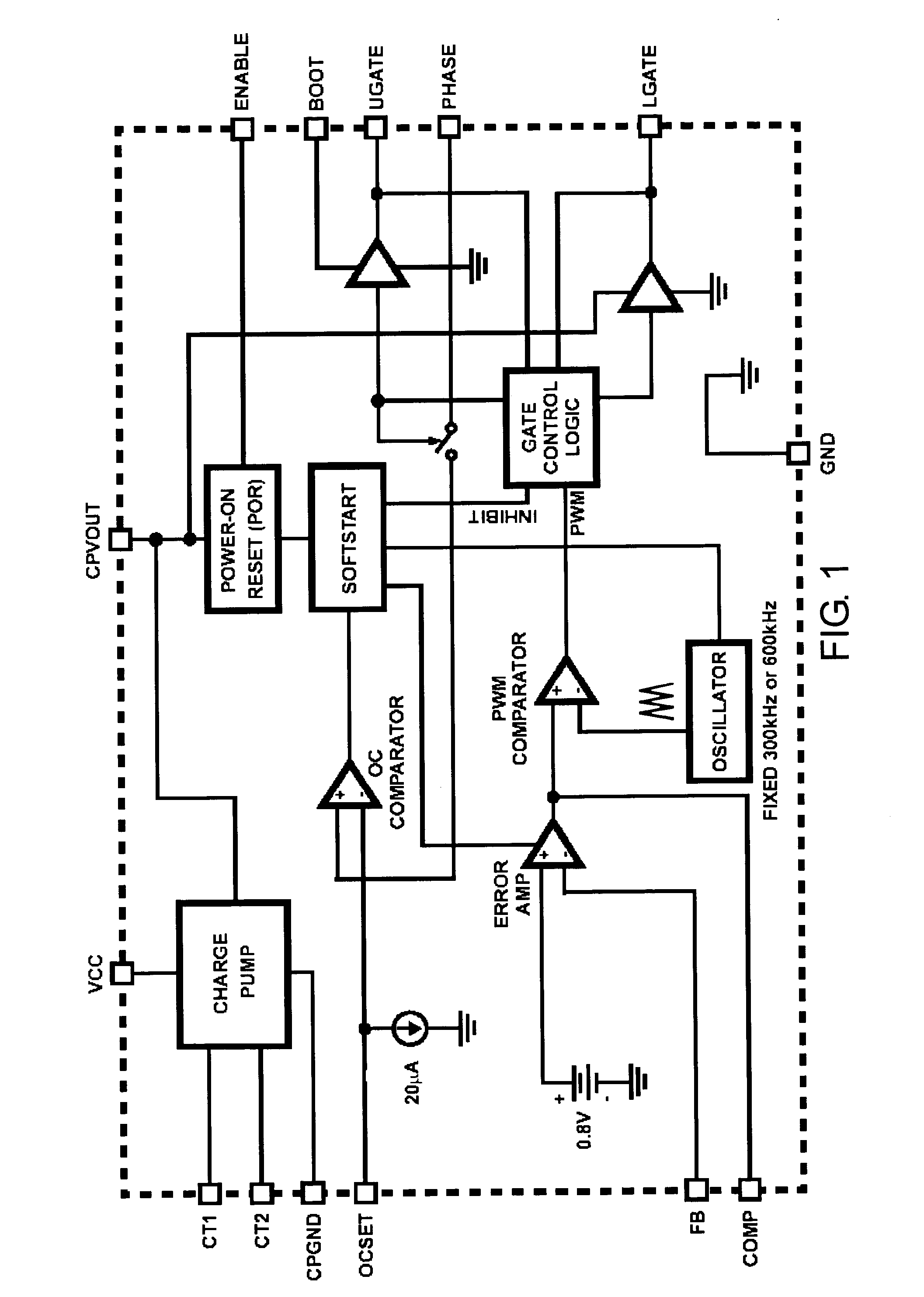
[0024]FIG. 1 shows the internal block diagram of a typical PWM controller, this one is Intersil's ISL6526. This control IC is intended for use in constructing synchronous buck DC / DC converters. Input power, Vin, is supplied to the IC via the Vcc pin. Pins Ugate and Lgate drive gates of external power MOSFETs. The IC also contains an internal reference, an error amp, an oscillator, and most of the other circuitry required to perform PWM-controlled switching of the external power MOSFETs.

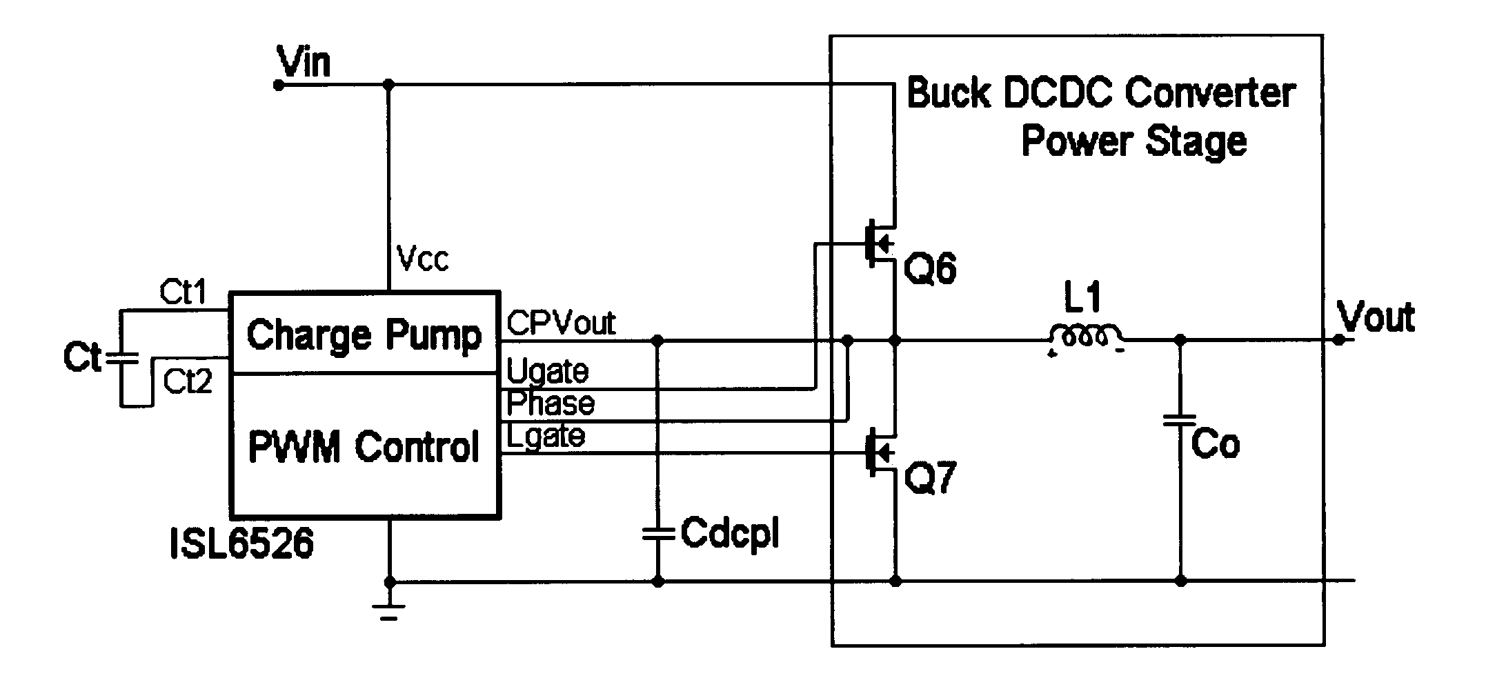
[0025] The essence of a typical implementation, that of a synchronous buck DCDC converter using an Intersil ISL6526 control IC, is shown in FIG. 2. Power MOSFETs Q6 and Q7 are turned on alternately, connecting L1 to either Vin or Ground. L1 and Co form a 2nd-order LC filter, smoothing the switching action of Q6 and Q7, and providing an essentially constant voltage, Vout.

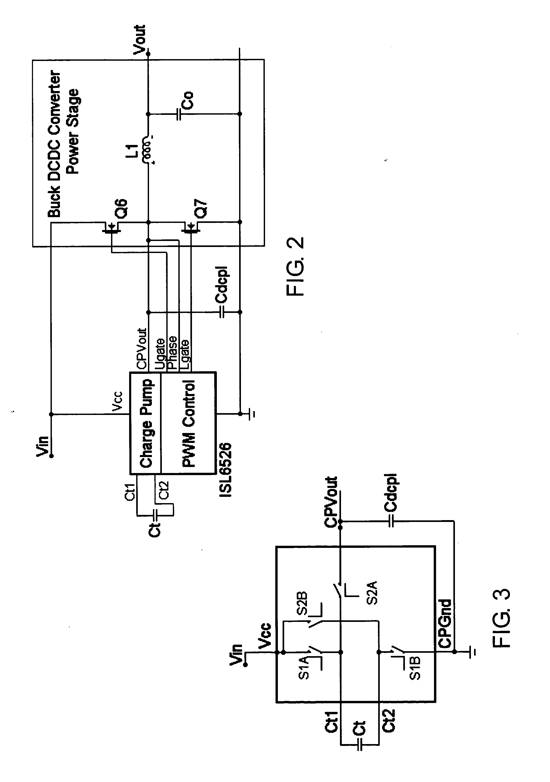
[0026] Of note is the Charge Pump section of the ISL6526. T...


PUM


Abstract

A charge pump generates gate control voltage in a DC / DC converter. The input voltage to the charge pump may vary. To reduce noise at higher input voltages, a variable resistance is included in the charge pump and that resistance is controlled to vary with the input voltage.

Description

RELATED APPLICATION [0001] This application is a continuation-in-part of U.S. Application identified by Attorney Docket No. 1465.2017-000 entitled “Charge Pump with Reduced Noise” filed on Jan. 23, 2004 with Thomas Farkas, Abram P. Dancy, Leif E. LaWhite and Martin F. Schlecht as inventors, which claims the benefit of U.S. Provisional Application No. 60 / 525,058, filed on Nov. 25, 2003. The entire teachings of the above applications are incorporated herein by reference.BACKGROUND OF THE INVENTION [0002] Power converters, such as non-isolated DC / DC down converters, are often built using integrated control circuits. These control IC's direct the operation of the power converter's power stage, and they implement various control functions that are required to create a well-behaved power converter under all operating conditions. [0003] One such control function provided by some control IC's is that of a bias supply to provide power to the controller's internal circuitry and to the driver ...

Claims


Application Information

Patent Timeline
Patent Type & Authority Applications(United States)
IPC IPC(8): H02M1/00H02M3/07H02M3/158
CPCH02M1/32Y02B70/1466H02M3/1588H02M3/07Y02B70/10
Inventor FARKAS, THOMASDANCY, ABRAM P.LA WHITE, LEIF ESCHLECHT, MARTIN F.
Owner SYNQOR
Why Eureka
Try Eureka