Synchronous Rectifier Control Circuit and Method

Active Publication Date: 2009-10-29
INFINEON TECH AUSTRIA AG
View PDF3 Cites 58 Cited by
  • Summary
  • Abstract
  • Description
  • Claims
  • Application Information

AI Technical Summary

Benefits of technology

[0009]These and other problems are generally solved or circumvented and technical advantages are generally achieved by preferred embodiments of the present invention which provide an efficient and reliable detection of the primary gate turn on and thus enable efficie

Problems solved by technology

Shoot through means that the converter output is shorted through the SR transistor and the transformer secondary side winding and the output capacitor is unnecessarily discharged.
Additionally, this shoot through may cause over current at the primary side and disturb proper operation of the converter.
Besides these, the system efficiency and EMI performance may be negatively influenced, as well.
A first disadvantage of these approaches is that they require added components, and reliability of operation of the secondary side power regulation circuits is not assured over a range of conditions which may occur in different voltage converter applications.
However, this circuit is not able to distinguish an oscillation or noise event from a true pri

Method used


Image

  • Synchronous Rectifier Control Circuit and Method
  • Synchronous Rectifier Control Circuit and Method
  • Synchronous Rectifier Control Circuit and Method

Examples


Embodiment Construction

[0028]The making and using of the presently preferred embodiments are discussed in detail below. It should be appreciated, however, that the present invention provides many applicable inventive concepts that can be embodied in a wide variety of specific contexts. The specific embodiments discussed are merely illustrative of specific ways to make and use the invention, and do not limit the scope of the invention.

[0029]The present invention will be described with respect to preferred embodiments in a specific context, namely a switched-mode power converter. The invention may also be applied, however, to other circuits where an SR is used.

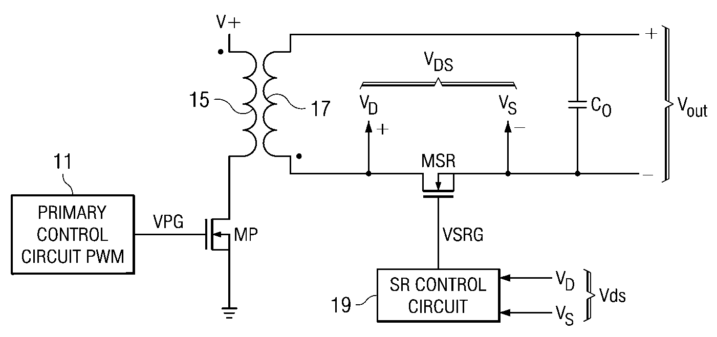
[0030]With reference now to FIG. 1, there is shown an exemplary power converter circuit with flyback converter incorporating the features of embodiments of the present invention. In FIG. 1, a transformer of primary side coil 15 and secondary side coil 17 is depicted. A primary control circuit pulse width modulator is shown driving the gate voltage VPG...


PUM


Abstract

Circuit and method for controlling a synchronous rectifier. A circuit for monitoring the drain to source voltage of an SR transistor in a secondary side circuit of a voltage converter is disclosed, having a circuit for generating a gate control circuit for the SR MOSFET; the circuit preventing subsequent gate control signals until a primary turn on detection signal is received. In another embodiment a circuit for generating the primary turn on detection signal is provided. A method for controlling an SR transistor is disclosed comprising monitoring the drain to source voltage of the SR MOSFET, generating a gate control output, and preventing subsequent gate control output signals until a primary turn on detection signal is received. In another method embodiment a method for generating the primary turn on detection signal is disclosed. An SR embodiment incorporating the control circuit embodiments is disclosed.

Description

TECHNICAL FIELD[0001]The present invention relates generally to a circuit and method to improve the operation of a switched-mode power supply converter, and more particularly, to a circuit and method for efficient operation of a DC-DC converter circuit using a synchronous rectifier (SR).BACKGROUND[0002]Generally, a rectifier is needed in a switching mode power supply system to provide a DC output voltage from an input voltage. An SR can improve the power conversion efficiency by reducing the conduction losses in the rectifier device. Recently, metal oxide semiconductor field effect transistor (MOSFET) devices have been used as the SR due to low conduction losses of a properly selected MOSFET in these applications.[0003]In MOSFET SR circuits, turn-on and turn off of the SR transistor must be synchronized with the control signal of the primary switch. Taking the flyback converter as an example in this text, the SR transistor is turned “off” by a gating signal (a potential at the gate ...

Claims


Application Information

Patent Timeline
IPC IPC(8): H02M7/04H03K17/687
CPCH02M1/08Y02B70/1475H02M3/33592H02M1/38Y02B70/10
Inventor HU, JING
Owner INFINEON TECH AUSTRIA AG
Why Eureka
Try Eureka