
Electric vehicle inverter protective device and method

A technology for electric vehicles and protection devices, applied in the direction of emergency protection circuit devices, electrical components, etc., can solve safety hazards, no inverter overvoltage, undervoltage, overcurrent, short circuit protection, inverter reliability, and life. And the functional requirements are not very high, to achieve the effect of protecting safe operation and mutual interference guarantee

Inactive Publication Date: 2016-04-20
UNITED AUTOMOTIVE ELECTRONICS SYST
View PDF9 Cites 56 Cited by
  • Summary
  • Abstract
  • Description
  • Claims
  • Application Information

AI Technical Summary

Problems solved by technology

Inverters are used in industrial occasions. Since the equipment does not have very high requirements on the reliability, life and function of the inverter, industrial inverters often use some relatively simple drive schemes, which do not meet the needs of inverters. Real-time monitoring of some key parameters (such as bus voltage, IGBT temperature, etc.) during inverter operation, and no comprehensive and timely protection for overvoltage, undervoltage, overcurrent, short circuit and other working conditions that may occur in the inverter
At the same time, there is no systematic isolation design and verification for high and low voltage circuits. Simply applying industrial inverters to electric vehicles will lead to various safety hazards during the use of electric vehicles.

Method used


Image

  • Electric vehicle inverter protective device and method
  • Electric vehicle inverter protective device and method

Examples


Embodiment Construction

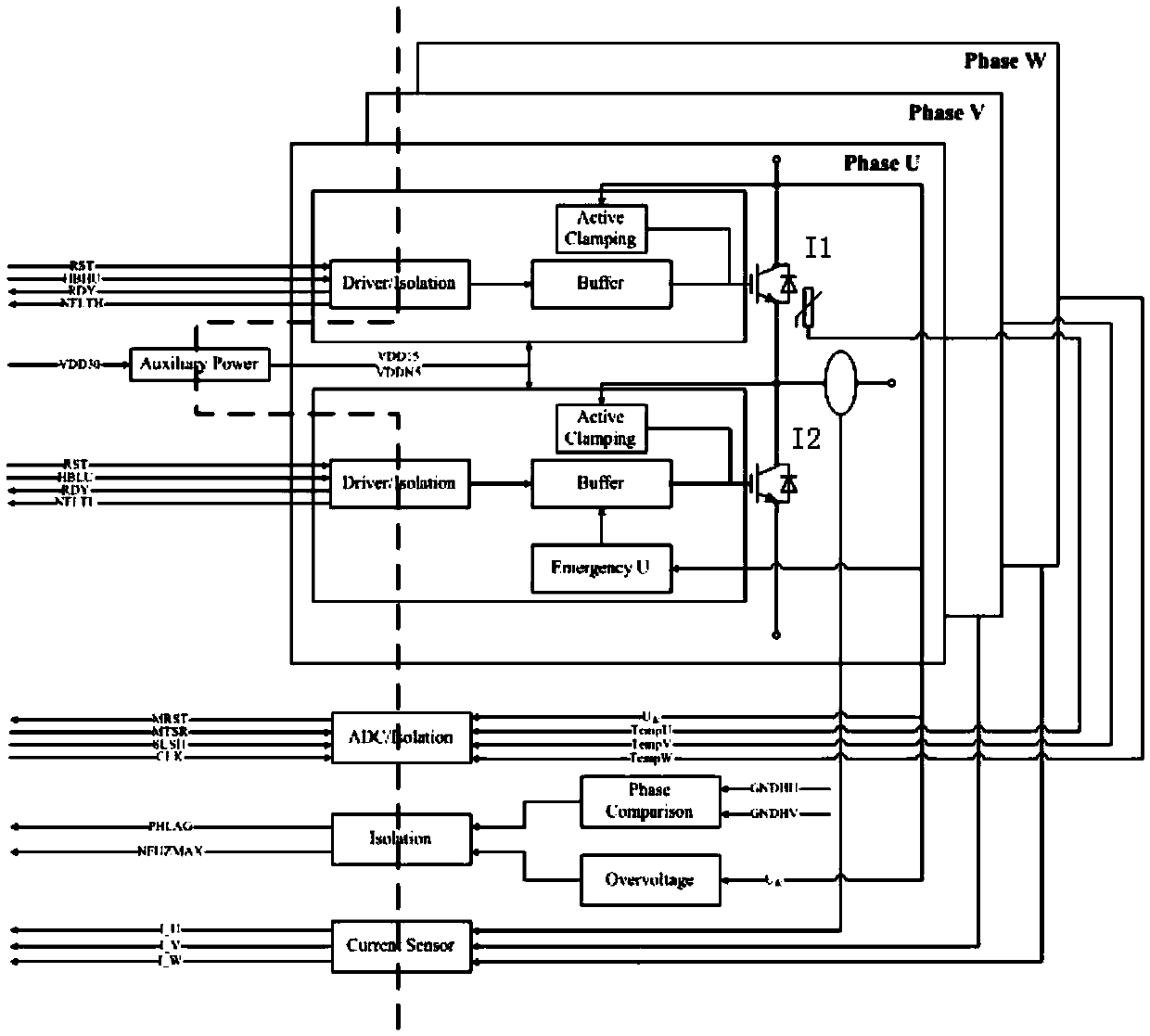
[0032] Such as figure 1 As shown, an embodiment of the electric vehicle inverter protection device provided by the present invention includes: an inverter controller (not shown in the figure), a drive circuit Driver, a buffer circuit Buffer, an auxiliary power supply AuxiliaryPower, an emergency circuit Emergency, and a bus voltage Detection circuit Overvoltage, high and low voltage isolation circuit Isolation, AD conversion circuit ADC, phase comparison circuit PhaseComparison, three-phase IGBT temperature detection circuit (not shown in the figure), three-phase current sensor CurrentSensor, active clamping module ActiveClamping, IGBT short circuit detection circuit (not shown in the figure); and the first IGBTI1 and the second IGBTI2 in series, the emitter of the first IGBTI1 is connected to the collector of the second IGBTI2, the collector of the first IGBTI1 is connected to the positive pole of the bus voltage, and the emitter of the second IGBTI2 is connected to the negat...


PUM


Abstract

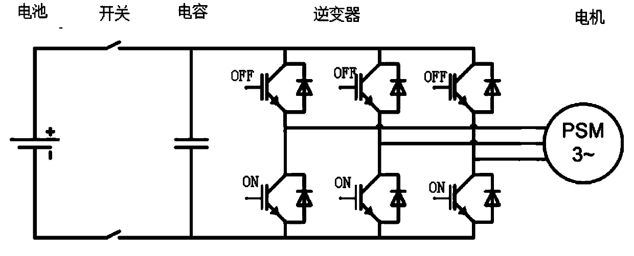
The invention provides an electric vehicle inverter protective device. A gate control signal is output to the gate of an IGBT through a driving circuit and a buffer circuit. An auxiliary power supply converts the power of an inverter controller into voltage controlling the on-off state of the IGBT and supplying power to the driving circuit. A bus voltage detection circuit determines whether bus voltage is higher than a bus high-voltage threshold value and outputs a voltage comparison signal to the inverter controller. An emergency circuit is powered by the bus voltage and outputs a gate signal to control the conduction of IGBTs at a three-phase lower half-bridge in order that the inverter is in an active short-circuit mode. Further, the inverter controller may output a reset signal to reset the driving circuit. The invention further provides an electric vehicle inverter protective method. The electric vehicle inverter protective device provides an active safe mode for the trailed condition of an electric vehicle, may detect the operating parameter of the inverter in real time, may isolate the high-voltage power from the low-voltage power of the inverter, and performs active protection on an electric vehicle inverter.

Description

technical field [0001] The invention relates to the field of automobiles, in particular to an inverter protection device for electric vehicles. The invention also relates to an electric vehicle inverter protection method. Background technique [0002] With the formulation of new national fuel consumption regulations, the development of new energy vehicles, especially electric vehicles, is becoming more and more rapid. Unlike traditional cars that burn oil to drive the vehicle, electric vehicles use a motor controller to convert the DC power of the vehicle's high-voltage battery into AC power that can drive the motor to rotate, and then drive the vehicle. The core component of electric energy conversion in the motor controller is the inverter. In order to ensure the quality and user experience of electric vehicles, the inverter, as an important part of the vehicle power system, must be reliable, Stable operation not only requires high requirements for important components o...

Claims


Application Information

Patent Timeline
IPC IPC(8): H02H7/122
CPCH02H7/122H02H7/1222H02H7/1225H02H7/1227
Inventor 于梦园周宣
Owner UNITED AUTOMOTIVE ELECTRONICS SYST
Learn More