Optical system for forming a real image in space

Active Publication Date: 2005-05-26
PC MIRAGE
View PDF11 Cites 64 Cited by
  • Summary
  • Abstract
  • Description
  • Claims
  • Application Information

AI Technical Summary

Problems solved by technology

However, optical system 20, while of very compact design, has a relatively low efficiency in terms of light throughput and exhibits poor contrast at non-normal, i.e., off-center or oblique, viewing angles.
However, DBEF 40 and first and second linear polarizers 32, 60 are absorptive in nature and result in losses in terms of light throughput.
For example, the type of quarter wave retarder used for first and second quarter wave retarders 44, 56 is of a drawn polyvinyl alcohol (PVA) type that characteristically exhibits poor retardance uniformity and has poor performance over time owing to inherent propensity of these types of polariz

Method used


Image

  • Optical system for forming a real image in space
  • Optical system for forming a real image in space
  • Optical system for forming a real image in space

Examples


Embodiment Construction

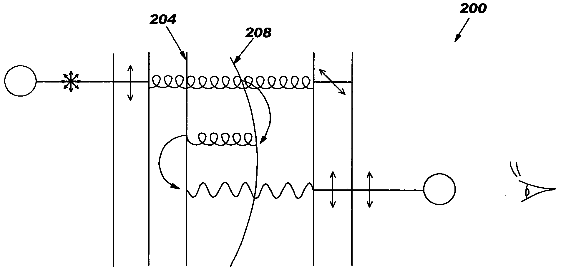
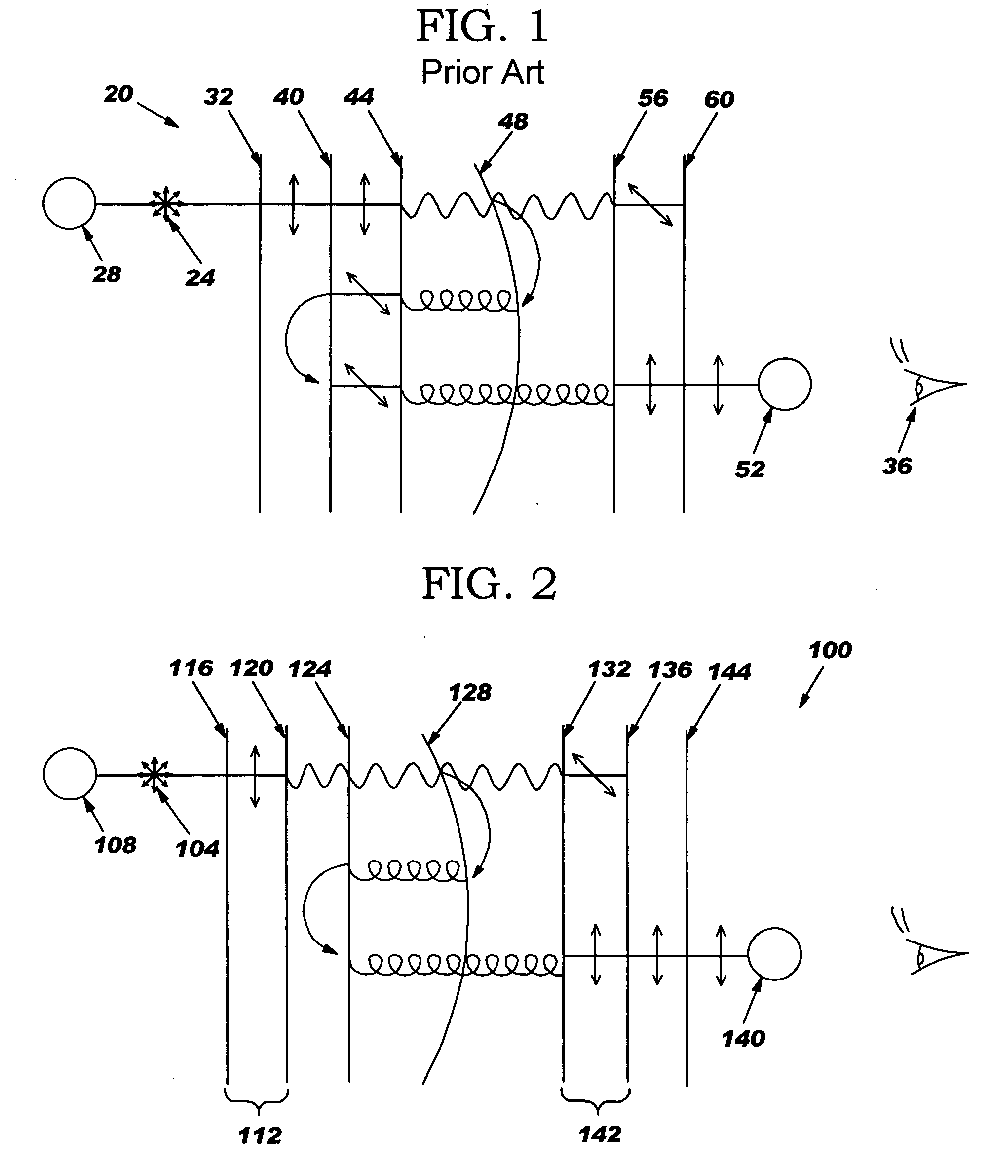
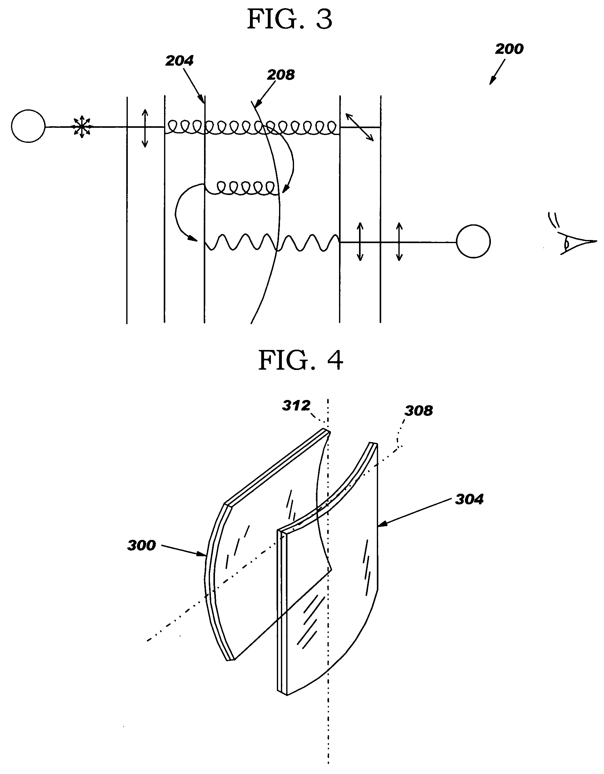
[0022] A goal of the present invention is to project a brighter real image into space while improving the off-angle response and manufacturability of real image optical systems, such as the optical system of U.S. Pat. No. 6,262,841 discussed in the background section above in connection with FIG. 1 (optical system 20), using polarizing and reflecting techniques to create a compact imaging system with a wide field of view. Several improvements for enhancing the image characteristics of such optical systems are disclosed. Generally, a basic premise of all three performance enhancements is either achieving greater “cooperation” between the polarizing elements (i.e. better, or “matched,” bandwidth response) or improving the losses due to absorption within the polarizing elements, depending upon the enhancement. U.S. Pat. No. 6,262,841 is incorporated by reference herein in its entirety and is referred to below as the “Dike patent.”

[0023] Known optical system 20 of FIG. 1 utilizes a refl...


PUM


Abstract

An optical system (100, 200, 400, 500) that projects a real image (140, 412, 504) into space and includes one or more features located along the optical path that enhance the viewability of the real image. The optical system includes a converging element (128, 208, 416, 528) for converging a portion of source light (104, 516) so as to form the real image. One viewability-enhancing features is the use of a broadband reflector-polarizer (124, 208, 408, 532) having high transmitting and reflecting efficiencies. Another viewability-enhancing features is the use of polarizing elements (116, 124, 136, 408, 420, 424) having substantially matched bandwidth responses and/or comprising an achromatic design. An additional viewability-enhancing feature is the use of a wide-view film (144) to increase the viewing angle of the image.

Description

FIELD OF THE INVENTION [0001] The present invention generally relates to the field of optics and, more particularly, to an optical system for forming an image in space. BACKGROUND OF THE INVENTION [0002] Optical systems capable of forming images from illuminated objects find numerous and important applications in areas such as advertising, marketing and product exhibition, as well as other more esoteric functions such as simulation. It is advantageous for such systems to be compact in size, have a wide field of view and high contrast and be viewable in all ambient lighting conditions. [0003] Many real image optical systems, e.g., real image projectors, are designed to create an image wherein the desired image appears against a black background. In a real image projector for, say, gaming applications, a floating, real image of a character is projected into space. The psychological impact of this image is greatest if the game elements appear bright, sharply defined and of high contras...

Claims


Application Information

Patent Timeline
IPC IPC(8): G02B5/30G02B17/06G02B27/00G02B27/01G02B27/28G02B30/25
CPCG02B5/30G02B27/0101G02B27/28G02B2027/012G02B2027/0123G02B27/2292G02B2027/0121G02B2027/0118G02B30/56
Inventor DIKE, BRUCE D.
Owner PC MIRAGE
Why Eureka
Try Eureka