Image signal processing method, image signal processing device, image signal processing program and integrated circuit device

Inactive Publication Date: 2005-05-26
PANASONIC CORP
View PDF4 Cites 26 Cited by
  • Summary
  • Abstract
  • Description
  • Claims
  • Application Information

AI Technical Summary

Benefits of technology

[0033] According to the image signal processing method of a thirteenth aspect of the present invention, the post-processing includes a process for eliminating a block noise by using the estimated coding parameters.
[0055] The eighteenth aspect of the present invention has the effect that the post-processing circuit can perform the post-processing independently of the decoder by using the coding parameters estimated by the coding parameter estimation circuit. Namely, even if the post-processing circuit cannot obtain the coding parameters directly from the decoder, noise of the decoded image can be reduced independently of the specification of the decoder.

Problems solved by technology

Usually, the MPEG method has the disadvantage that low transmission bit rate (high compression ratio) in which the quantity of information is reduced substantially causes increase of conspicuous coding noise and deterioration of image quality.
This noise is caused by a variance of low frequency components between neighboring blocks and a lack of high frequency components.
This noise is caused by a lack of high frequency components within a block.
However, if the coding parameters cannot be obtained from the decoding portion 012, the post-processing portion 011 cannot perform the noise reduction as described above.
For example, when a post-processing portion is being added to a decoder (that is already developed) so as to improve the image quality of a reproduced image, there may be the problem that the coding parameters cannot be transmitted because of a difference in specification between the decoder and the post-processing portion.

Method used


Image

  • Image signal processing method, image signal processing device, image signal processing program and integrated circuit device
  • Image signal processing method, image signal processing device, image signal processing program and integrated circuit device
  • Image signal processing method, image signal processing device, image signal processing program and integrated circuit device

Examples


first embodiment

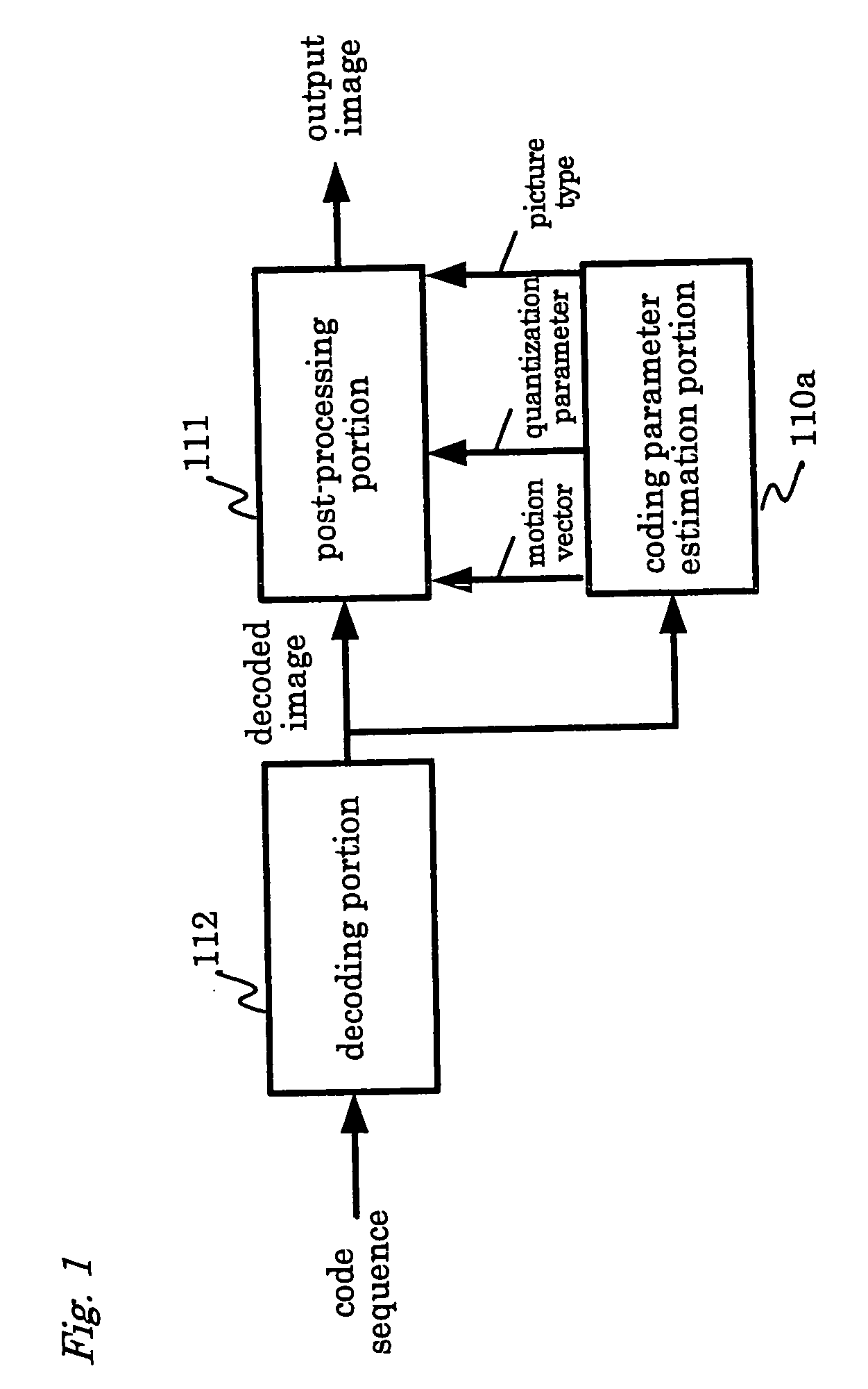
[0084]FIG. 1 is a block diagram of a first embodiment of the present invention, which includes a coding parameter estimation portion 110a, a post-processing portion 111 and a decoding portion 112. This structure is different from the conventional one shown in FIG. 27 in that it includes the coding parameter estimation portion 110a and coding parameters are not delivered from the decoding portion 112.

[0085] The decoding portion 112 decodes a code sequence that has been entered (or “entered code sequence”) and delivers the decoded image to the coding parameter estimation portion 110a and the post-processing portion 111.

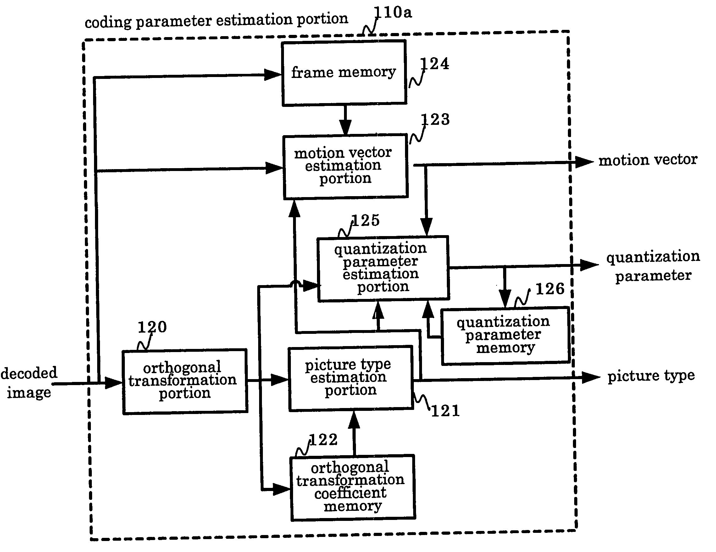
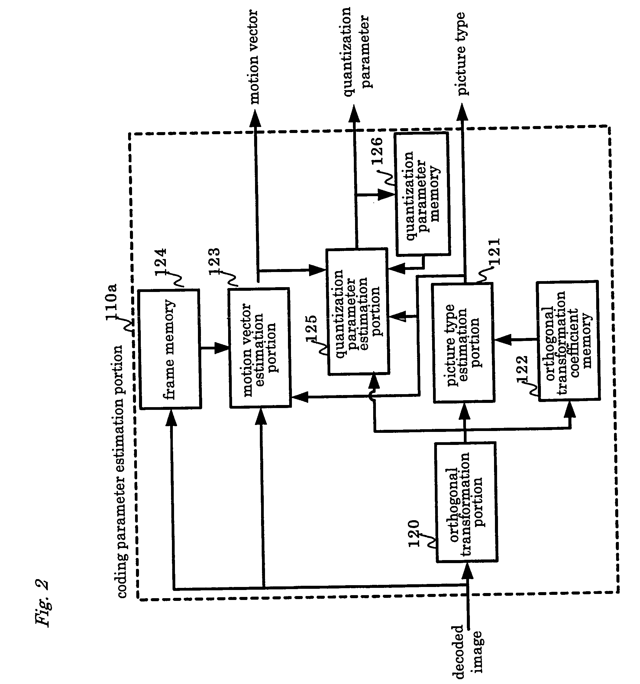
[0086] The coding parameter estimation portion 110a receives the decoded image as an input from the decoding portion 112 and estimates a quantization parameter that was used for coding, a picture type and a motion vector from the decoded image that has been received. The estimated quantization parameter, picture type and motion vector are delivered to the post-process...

second embodiment

[0127] A block diagram of a second embodiment of the present invention is the same as the first embodiment shown in FIG. 1 except for the coding parameter estimation portion 110a. Hereinafter, the coding parameter estimation portion 110a will be described.

[0128]FIG. 10 is a block diagram showing the internal structure of the coding parameter estimation portion 110a of the second embodiment. As shown in FIG. 10, the coding parameter estimation portion 110a includes an orthogonal transformation portion 220 for performing the DCT, a picture type estimation portion 221 for estimating the picture type of the decoded image, an orthogonal transformation coefficient memory 222 for storing DCT coefficients of the previous decoded image, a motion vector estimation portion 223 for estimating the motion vector, a frame memory 224 for storing the previous decoded image, a differential image calculation portion 225 for determining a differential image between the decoded image and the reference ...

third embodiment

[0137]FIG. 12 is a block diagram showing the third embodiment of the present invention, which includes a coding parameter estimation portion 110b, the post-processing portion 111 and the decoding portion 112.

[0138] The coding parameter estimation portion 110b receives the decoded image as an input from the decoding portion 112 and estimates the quantization parameter and the picture type of the decoded image from the entered decoded image in accordance with a predetermined method. Then, the estimated quantization parameter and the picture type are delivered to the post-processing portion 111.

[0139] The post-processing portion 111 receives the decoded image from the decoding portion 112, and the quantization parameter and the picture type from the coding parameter estimation portion 110b as each input, so as to eliminate block noise by the conventional method using the quantization parameter and the picture type.

[0140] Next, a structure of the coding parameter estimation portion 1...


PUM


Abstract

An image signal processing method, an image signal processing device and an image signal processing program are provided for performing post-processing, independently of the specification of a decoder. A coding parameter estimation portion estimates a quantization parameter, a picture type and a motion vector that were used for coding by using a decoded image entered from a decoding portion. The estimated quantization parameter or the like is sent to a post-processing portion. The post-processing portion performs the post-processing by using the entered quantization parameter, picture type and motion vector for eliminating block noise or mosquito noise.

Description

BACKGROUND OF THE INVENTION [0001] 1. Field of the Invention [0002] The present invention relates to an image signal processing method, an image signal processing device, an image signal processing program and an integrated circuit device. More specifically, the present invention relates to an image signal processing method, an image signal processing device, an image signal processing program and an integrated circuit device for improving the image quality of a decoded image of a block-by-block compressed and coded image. [0003] 2. Description of the Prior Art [0004] Recently, as a high efficiency compressing and coding method of images in the broadcasting or storage fields, an MPEG (Moving Picture Experts Group) method is widely used. The MPEG method realizes coding of an image by reducing spatial and temporal redundancy of the image. Picture types in the MPEG method are roughly divided into two images; one is an intra-frame coded image that is coded by utilizing a spatial depende...

Claims


Application Information

Patent Timeline
IPC IPC(8): H04N7/26
CPCH04N19/139H04N19/172H04N19/86H04N19/14H04N19/18H04N19/117
Inventor SUGIO, TOSHIYASUNISHI, TAKAHIROHORIIKE, KAZUYOSHI
Owner PANASONIC CORP
Why Eureka
Try Eureka