Peak-to-average reduction technique for multi-carrier power amplifiers

Inactive Publication Date: 2005-05-26
ALTERA CORP
View PDF4 Cites 9 Cited by
  • Summary
  • Abstract
  • Description
  • Claims
  • Application Information

AI Technical Summary

Benefits of technology

[0002] According to the invention, a low-cost RF peak-to-average reduction circuit, for use with multi-carrier RF power amplifier, uses a plurality of simple and accurate circuits in conjunction with intelligent signal processing to improve power handling of the multi-carrier RF power amplifier. By intelligent, it is meant that the peak-to-average reduction module has features of adaptability to the input samples, such as ability to consider the changes due to samples amplitude and phase. The peak-to-average reduction module uses the amplifier input which could be a baseband, an IF or RF signal as its input and condition the input before applying to the multi-carrier amplifier. The conditioning or peak-to-average reduction helps to boost the power handling of the amplifier or acts more linearly. The conditioning is based on pre-defined parameters stored in a lookup table for peak-to-average reduction. The inputs to the peak-to-average reduction should be within a limit that can be handled by the peak-to-average reduction module.

Problems solved by technology

This component has a major contribution in cost, power consumption, and size of the system.
The higher the linearity, the higher the power consumption, cost and size.

Method used


Image

  • Peak-to-average reduction technique for multi-carrier power amplifiers
  • Peak-to-average reduction technique for multi-carrier power amplifiers
  • Peak-to-average reduction technique for multi-carrier power amplifiers

Examples


Embodiment Construction

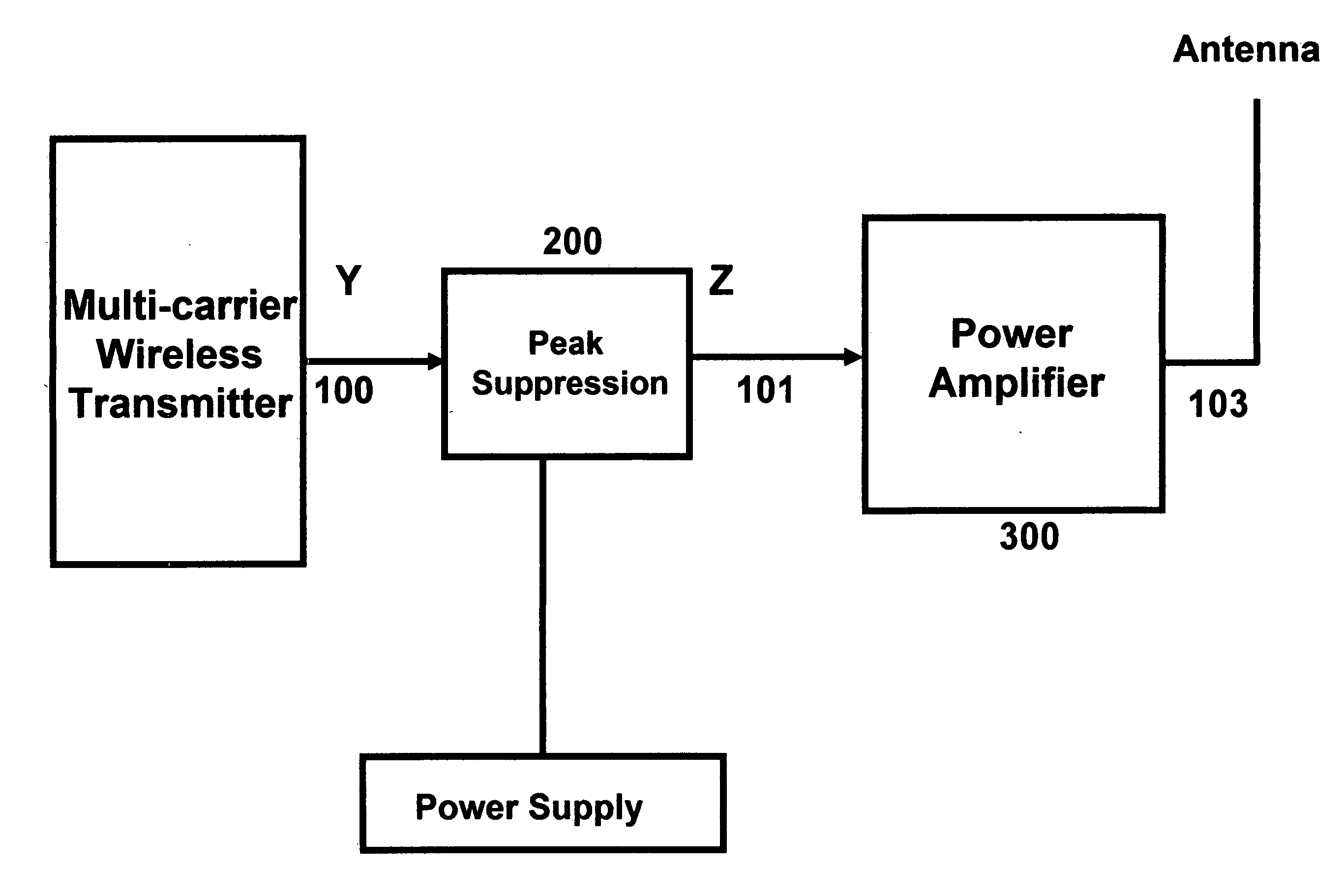
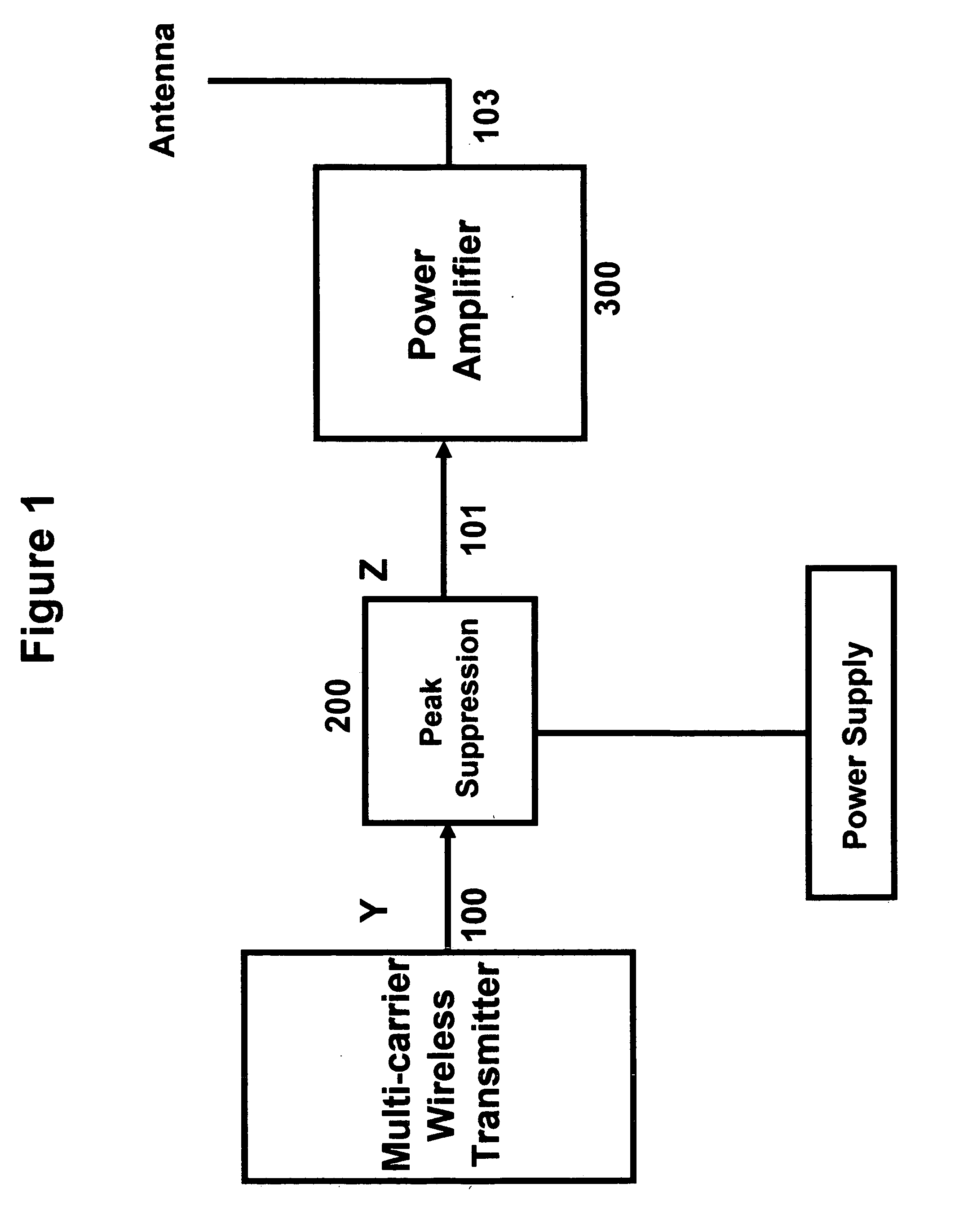
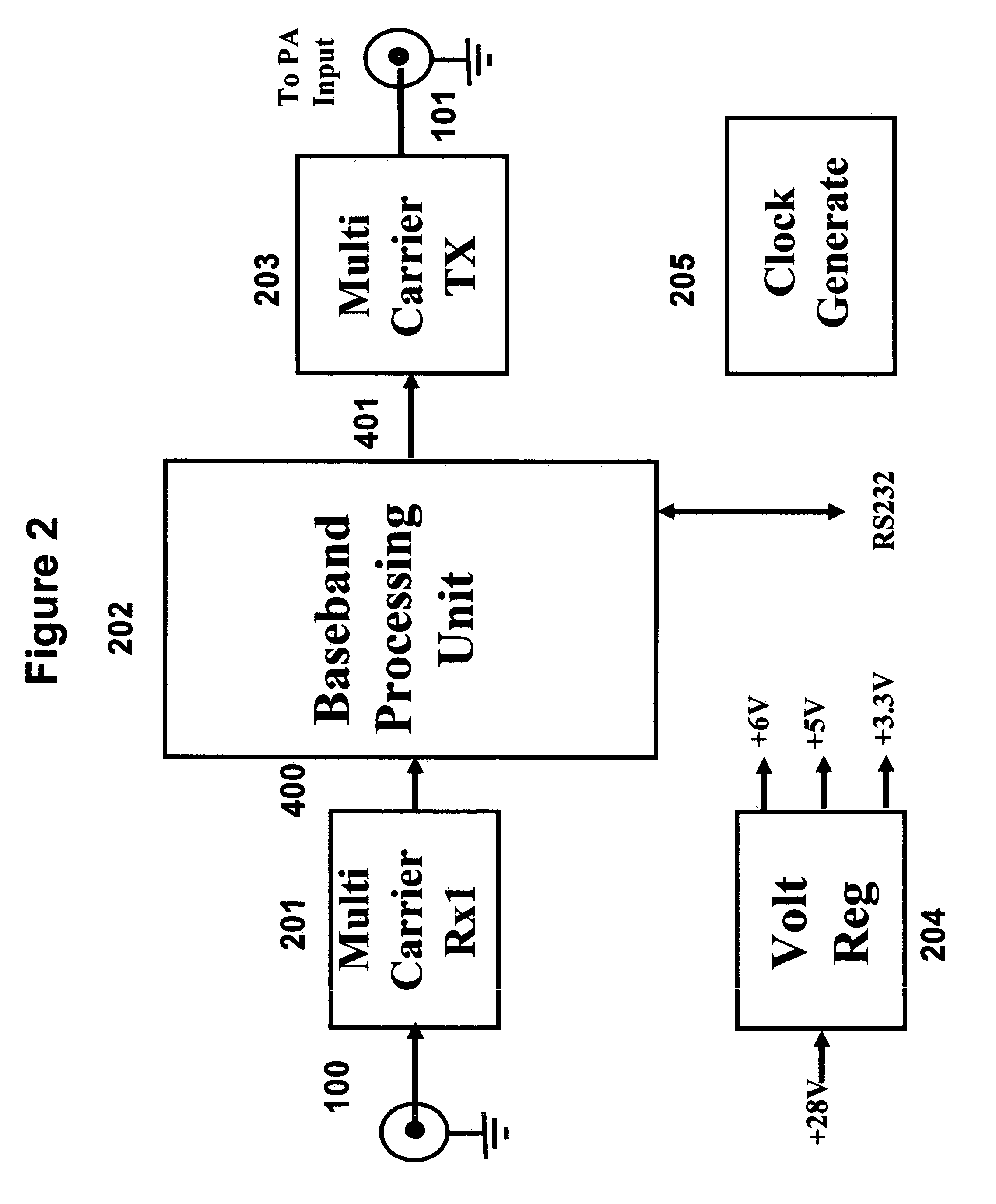
[0006] In a first preferred embodiment the peak-to-average reduction circuit monitors the signal strength of the multi-carrier input signal channels using the input receiver and finds the frequency and channel number of the input signals. In a second preferred embodiment of the invention, the peak-to-average reduction circuit uses sub-harmonic sampling to convert multi-carrier RF or IF signals to digital baseband signal. In a third preferred embodiment the input signal is conditioned or peak suppressed using the peak-to-average reduction data stored in a lookup tables before being transmitted to the amplifier. In a fourth embodiment the input signal is used to create the lookup table. In a fifth embodiment the digital baseband signal is further down converted to produce the individual carrier baseband signal. In a six embodiment the individual baseband signals are clipped and phase rotated using the associated lookup table before being individually filtered and up converted to recon...


PUM


Abstract

A technique for peak-to-average reduction of multi-carrier signals is described. The input to the multi-carrier power amplifier is modified by a peak-to-average reduction circuit, prior to being applied to the amplifier. The peak-to-average reduction circuit uses a phase generator to create appropriate phase for each carrier to suppress the peak of the multi-carrier signal. The peak-to-average reduction circuit clips the multi-carrier input signal's samples before applying any phase rotation if they exceed a predefined value. The input to the peak-to-average reduction circuit could be a baseband, an intermediate frequency (IF) or radio frequency (RF) signal. The peak-to-average reduction is performed in digital domain.

Description

BACK GROUND OF INVENTION [0001] The present invention relates to a peak-to-average reduction circuit to boost the out put power of a multi-carrier wireless RF power amplifier. The peak-to-average reduction circuit input could be baseband, intermediate frequency (IF), or RF signal. and its output is the peak-to-average reduced RF signal as a new input to the amplifier. In any wireless communication system one of the critical components is the power amplifier. This component has a major contribution in cost, power consumption, and size of the system. The main reason is the requirement of wireless radio communication system for linear power amplifiers. The higher the linearity, the higher the power consumption, cost and size. In order to minimize the cost, size and power consumption there is a need for techniques that overcome this problem. This invention conquers these challenges by using a simple and accurate peak-to-average reduction module used at the input to the power amplifier. ...

Claims


Application Information

Patent Timeline
IPC IPC(8): H04K1/02H04L27/26
CPCH04L27/2626H04L27/2614
Inventor ANVARI, KIOMARS
Owner ALTERA CORP
Why Eureka
Try Eureka