Shaping of structures of ceramic filters

Active Publication Date: 2018-05-10
LGS INNOVATIONS
View PDF0 Cites 1 Cited by
  • Summary
  • Abstract
  • Description
  • Claims
  • Application Information

AI Technical Summary

Benefits of technology

The patent text discusses the limitations of filter performance due to electromagnetic losses and the impact of geometry on filter performance. It suggests that by optimizing the shape of magnetic structures and dielectric sub-elements, the performance of filters can be improved by reducing RF losses and improving power handling. Specifically, the text proposes methods and devices for rounded, tapering, or chamfering the edges of resonator cavities to minimize current crowding and improve filter performance. Overall, the patent aims to provide a solution for improving the efficiency of filters while addressing their limitations.

Problems solved by technology

Filter performance may be limited by electromagnetic losses in materials used including dielectric material and materials used for conducting paths and pads.
Further, geometries of shapes of different elements or portions of elements may affect the performance of a given filter.

Method used


Image

  • Shaping of structures of ceramic filters
  • Shaping of structures of ceramic filters
  • Shaping of structures of ceramic filters

Examples


Embodiment Construction

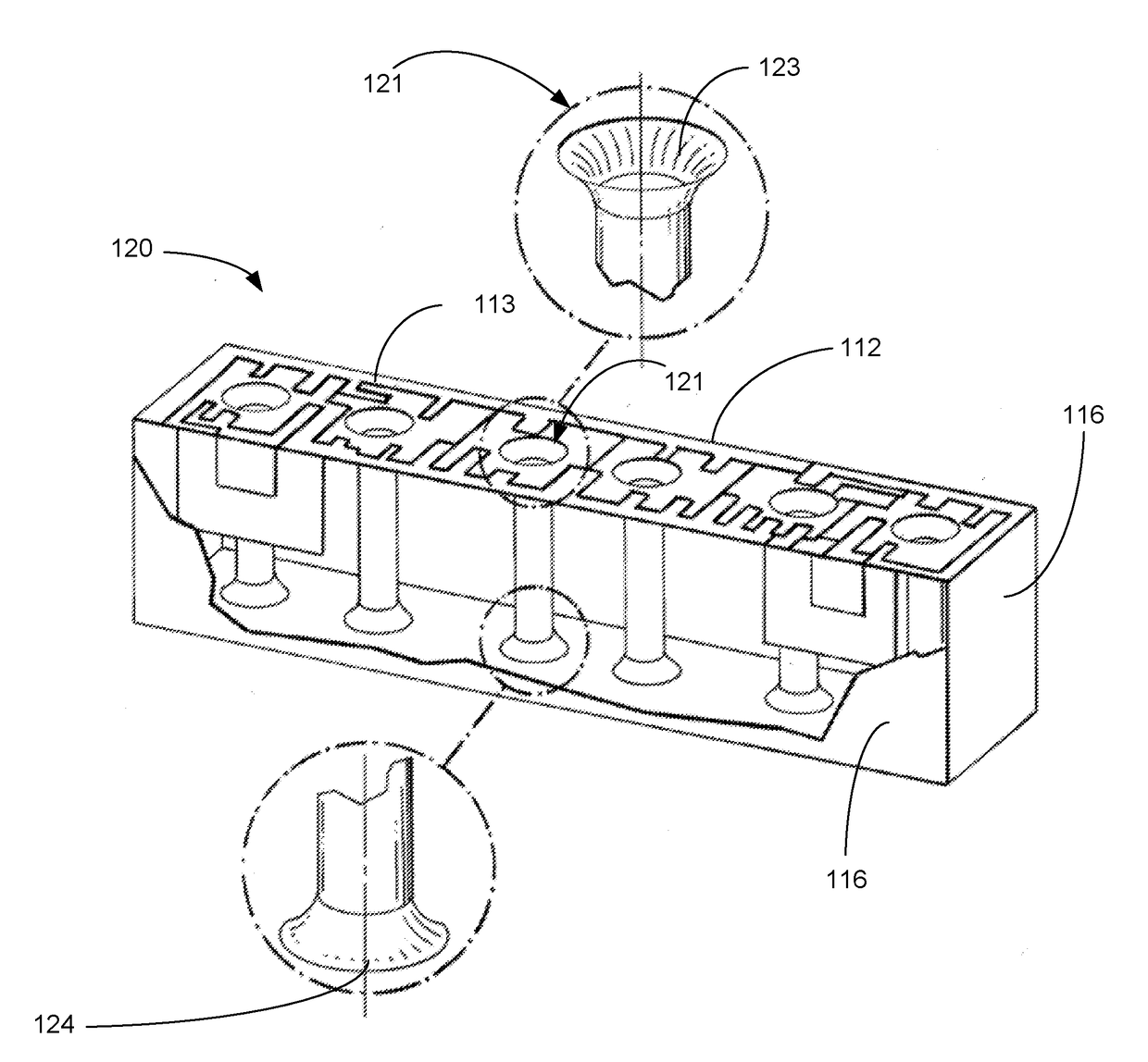
[0017]Disclosed herein are exemplary methods, systems, and apparatus associated with shaping structures of filters. The methods, systems, and apparatus for shaping structures of a filter may reduce RF losses and improve power handling, among other things.

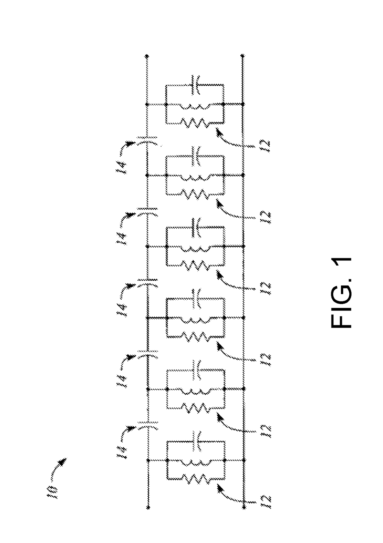
[0018]FIG. 1 illustrates an exemplary equivalent circuit for a monoblock filter. Conventionally, when equivalent circuits 10 are drawn for a monoblock filter, such as equivalent circuit 10, they do not show a complete model for a given monoblock filter. Most drawings or implementations of equivalent circuits 10 for a monoblock filter fail to incorporate real world equivalent resistive elements that play into the performance of a monoblock filter implemented using a given topology and given conductive material. In the equivalent circuit of FIG. 1 in reality there are resistive elements in all series paths—small resistance in series with all resistor (R), inductor (L), a capacitor (C)-(RLC) combinations 12 and in series with input and...


PUM


Abstract

The present application is directed to a filter and methods of making the same. The filter includes a block of dielectric material with a top surface including a patterned region, a bottom surface, and side surfaces. The filter also includes a through-hole extending through the block from the top surface to the bottom surface. The through-hole may include a top edge that connects the top surface with an inner wall of the through hole and a bottom edge that connects the bottom surface with the inner wall of the through hole. The top edge or bottom edges of the through-hole may be rounded, chamfered, or tapered.

Description

CROSS-REFERENCE TO RELATED APPLICATIONS[0001]This application claims the benefit of priority of U.S. Provisional Application No. 62 / 418,994 filed Nov. 8, 2016, entitled “Ceramic Filters With Improved Electrical Performance,” the contents of which is incorporated by reference in its entirety herein.FIELD[0002]This application is generally related to an apparatus and method for improving the Q factor of a ceramic filter.BACKGROUND[0003]In the basic ceramic block filter design, the resonators are formed by typically cylindrical passages, called resonator cavities (e.g., through-holes), extending through the block from the long narrow side to the opposite long narrow side. The block is substantially plated with a conductive material (e.g., metallized) on all but one of its six (outer) sides and on the inside walls formed by the resonator cavities. One of the two opposing sides containing resonator cavity openings is not fully metallized, but instead bears a metallization pattern designe...

Claims


Application Information

Patent Timeline
IPC IPC(8): H01P1/20H01P11/00
CPCH01P1/2002H01P11/007H01P1/2056H01P7/04
Inventor BURGESS, SCOTT WILLIAMNUMMERDOR, JR., JEFFERY JANBRANNON, ALAN SCOTT
Owner LGS INNOVATIONS
Why Eureka
Try Eureka