Coaxial resonator with dielectric disc

A coaxial resonator and dielectric technology, applied in the direction of resonators, waveguide devices, electrical components, etc., can solve the size problem, hinder the base station and other problems, achieve good contact, improve the quality factor, and improve the effect of power handling

Inactive Publication Date: 2018-08-03
TELEFON AB LM ERICSSON (PUBL)
View PDF5 Cites 2 Cited by
  • Summary
  • Abstract
  • Description
  • Claims
  • Application Information

AI Technical Summary

Problems solved by technology

[0007] Previous technology had size issues at low frequencies below 1G Hz, preventing smaller base stations

Method used


Image

  • Coaxial resonator with dielectric disc
  • Coaxial resonator with dielectric disc
  • Coaxial resonator with dielectric disc

Examples


Embodiment Construction

[0019] A dielectric material with a dielectric constant higher than about 80 with sufficient RF properties and reasonable cost is required to be able to use TM mode resonators for low frequency bands to maintain the same filter size as for high frequency bands. Unfortunately, authorized dielectric material suppliers have not been successful in developing dielectric materials with a dielectric constant above about 48 and with sufficient RF properties such as Q and temperature coefficient.

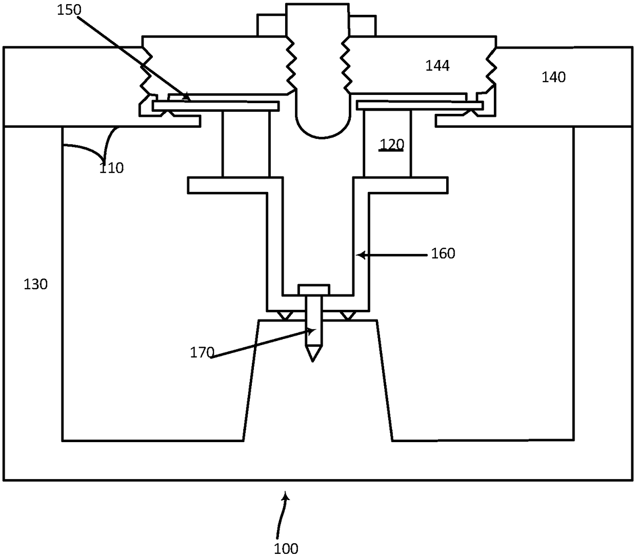
[0020] Embodiments herein relate to, for example, an improved resonator design that works with a quasi-TEM by adding a dielectric disk on top of a standard coaxial resonator made of metal. Such an embodiment enables smaller filters at lower frequencies below 1 GHz, eg allowing construction conventions to be maintained for different frequencies at the same size.

[0021] figure 1 is a cross-section of the filter assembly 100 according to an exemplary embodiment. The filter housing 110 inclu...


PUM


Abstract

A coaxial resonator (160) is provided. The coaxial resonator (160) has a first side (161) and a second side (162), the coaxial resonator comprising a dielectric disc (120) having a first surface (121), a second surface (122) and a hole, wherein the second side (162) of the coaxial resonator (160) is connected to the first surface of the dielectric disc (121), wherein the coaxial resonator (160) further comprises a conductive element (150) connected to second surface (122) of the dielectric disc. A filter (200) comprising a housing (110), comprising a lid/cover (140) and a chassis (130) havingone or more cavities (135) adapted for receiving a coaxial resonator (160) is also provided.

Description

technical field [0001] The present disclosure relates to coaxial resonators, and more particularly, to coaxial resonators having a dielectric disk and a metal element on top of the dielectric disk. Background technique [0002] The simplest form of a bandpass filter consists of multiple resonators arranged in such a way that the input signal is first input to the input port, then to the first resonator, then through the second resonator and the other resonators in sequence , until it reaches the last resonator and leaves the filter at the output port. [0003] For example, RF bandpass filters in base stations use air-cavity coaxial resonators. This technique is used to build filters used in base stations that handle medium to high power levels between 10-120W RF at frequencies around 500-3000MHz. [0004] Dielectric resonators are used to reduce filter size and achieve high Q in bandpass filters. The Q-value is the quality factor of a resonator, eg, the ratio between the ...

Claims


Application Information

Patent Timeline
Patent Type & Authority Applications(China)
IPC IPC(8): H01P1/205H01P7/04
Inventor A·莱泰夫H·雅哈P·杰泽耶夫斯基
Owner TELEFON AB LM ERICSSON (PUBL)
Why Eureka
Try Eureka