
Drive-section-isolated foup opener

a technology of drive section and opener, which is applied in the field of container openers, can solve the problems of reducing the number of guide slits, reducing the number of guide slits, and so as to maintain a high level of cleanliness in the clean room, the effect of reducing the number of cleaning slits

Inactive Publication Date: 2005-05-26
HIRATA & CO LTD
View PDF0 Cites 14 Cited by
  • Summary
  • Abstract
  • Description
  • Claims
  • Application Information

AI Technical Summary

Benefits of technology

[0009] An object of the present invention is to solve the above-mentioned problems in the conventional FOUP openers and to provide a FOUP opener which does not cause contamination of a clean room (a second control space) by contaminants generated by drives of horizontal- and vertical-movement mechanisms for a port door and a sensor; which does not allow entry of dust into a FOUP (first control space) or into the clean room from the ambient atmosphere.
[0010] Another object is to prevent adhesion of dust to the inside surface of a FOUP door and to the outside surface of the port door.
[0011] Yet another object is to prevent outflow of a large amount of highly clean air to the exterior of the clean room.

Problems solved by technology

Thus, there has been the problem that the drives, which are dust generators, contaminate the second control space 200, which must maintain a clean atmosphere.
As a result, the clean room 200 fails to maintain a high level of cleanliness.
Thus, restoration of cleanliness within the clean room 200 to a regular, high level consumes a considerably great amount of time and cost.
In order to enable a worker to work within the clean room 200, equipment for removing dust from the worker must be installed, thus incurring further cost.
Thus, the presence / absence, storage condition, and position of wafers 014 contained in the FOUP 010 cannot be detected with high accuracy, thus creating possible problems in transfer of the wafers.

Method used


Image

  • Drive-section-isolated foup opener
  • Drive-section-isolated foup opener
  • Drive-section-isolated foup opener

Examples


Embodiment Construction

[0029] An embodiment of the present invention will next be described in detail with reference to the drawings.

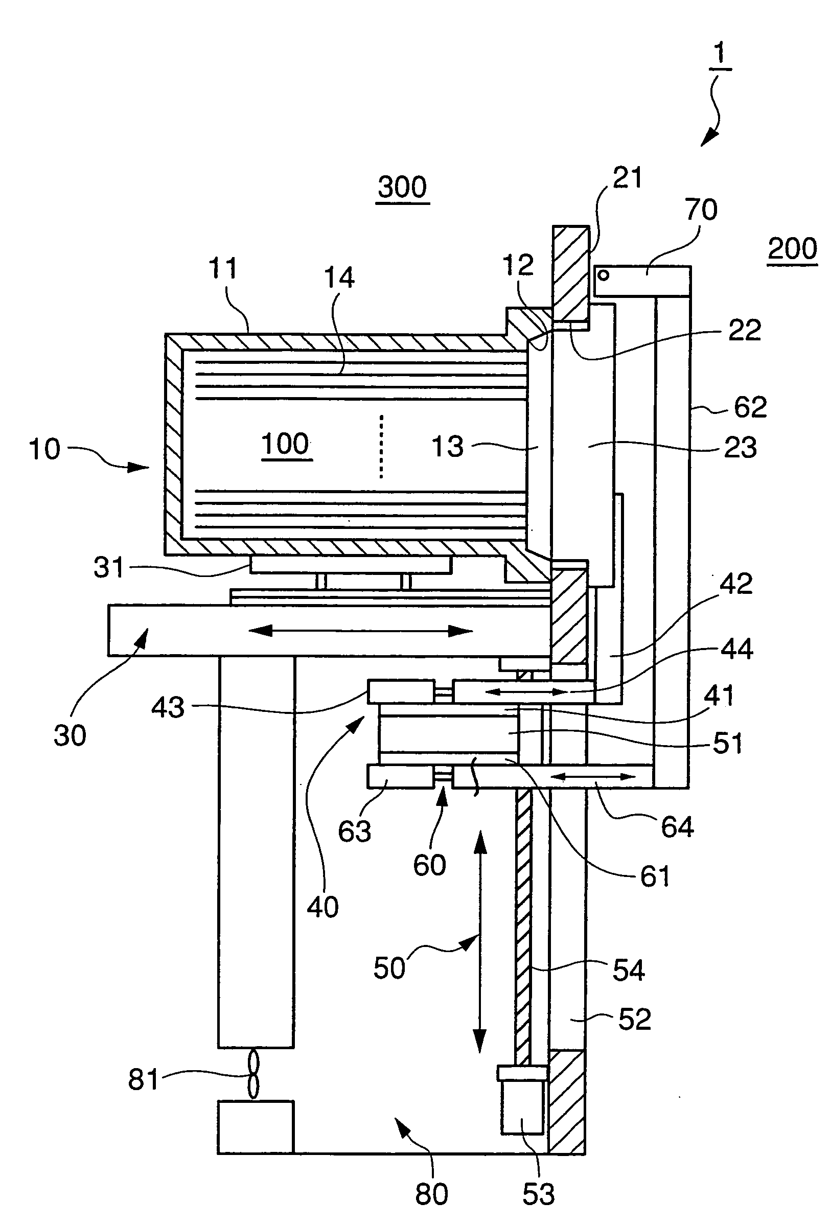
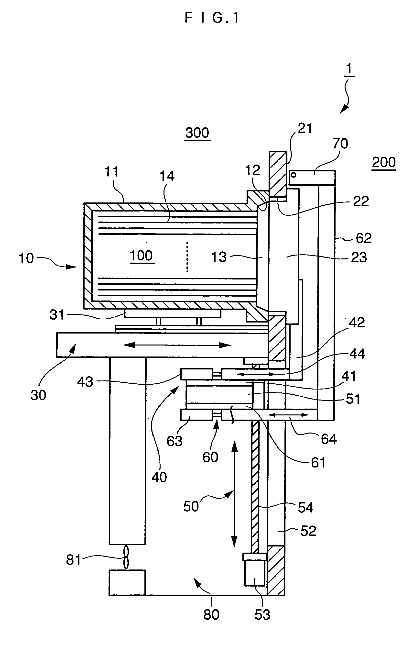
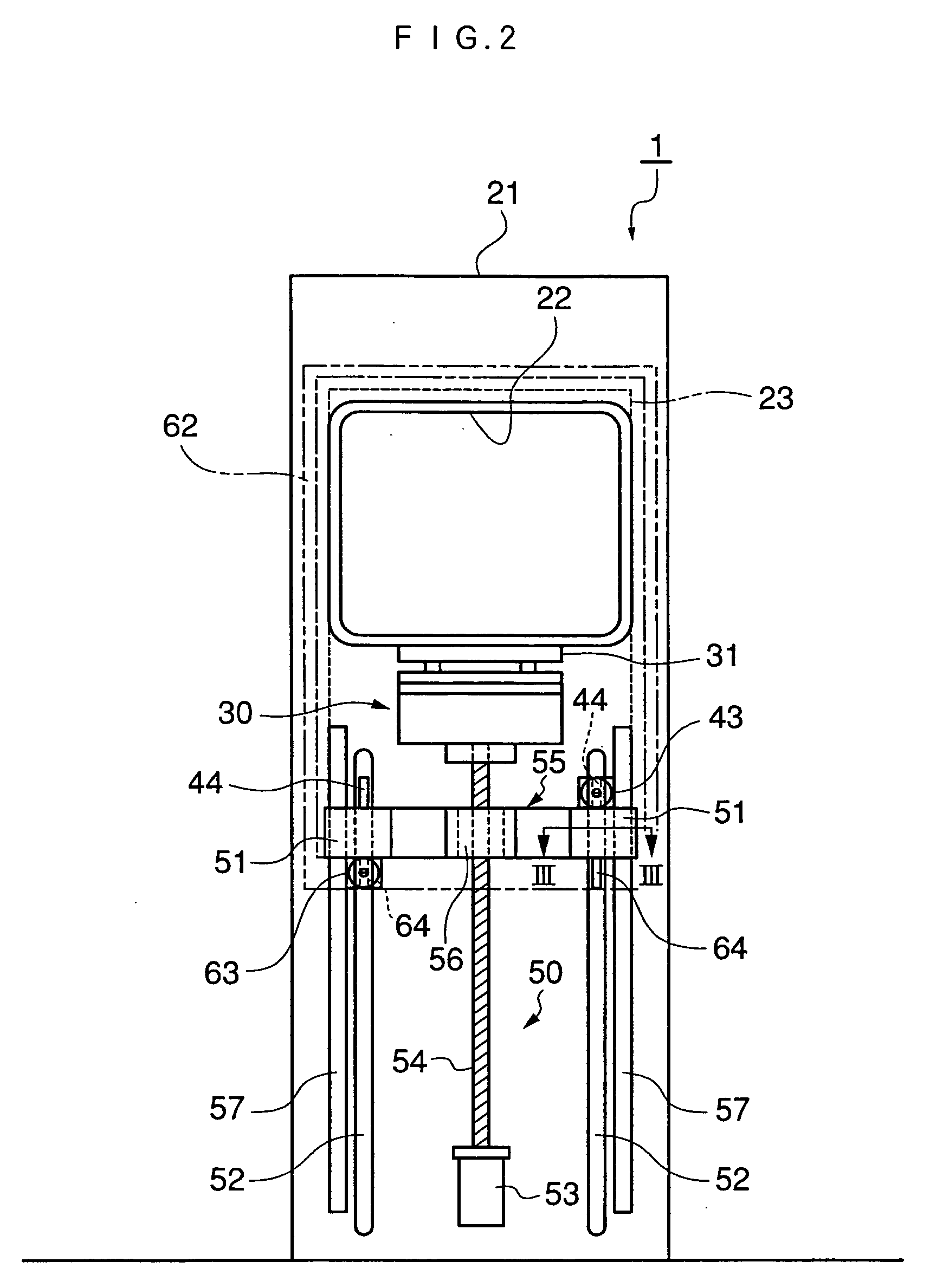
[0030] As shown in FIG. 1, a drive-section-isolated FOUP opener 1 of the present embodiment includes a FOUP 10 containing a plurality of semiconductor wafers 14 oriented horizontally and vertically arranged at predetermined intervals; a dock plate 31 for carrying and positioning the FOUP 10; a dock moving mechanism 30 for moving the dock plate 31 to a position for detachment / attachment of a FOUP door 13; a port door 23 including a detachment / attachment mechanism (not shown) for detaching / attaching the FOUP door 13 and a holder mechanism (not shown) for holding the FOUP door 13; a port plate 21 including an opening 22, the opening 22 being closed by the port door 23; a port door horizontal-movement mechanism 40 for horizontally moving the port door 23; a sensor horizontal-movement mechanism 60 for horizontally moving a sensor bracket 62, the sensor bracket 62 having a mappin...


PUM


Abstract

A drive-section-isolated FOUP opener opens and closes a door of a FOUP which contains a plurality of semiconductor wafers. The FOUP opener includes a dock plate for carrying and positioning the FOUP; a dock moving mechanism for moving the dock plate to a position for detachment / attachment of the FOUP door; a port door including a mechanism for releasably holding the FOUP door; a port plate including an opening closed by the port door; a port door horizontal-movement mechanism for horizontally moving the port door; a sensor horizontal-movement mechanism for horizontally moving a sensor bracket, the sensor bracket carrying a mapping sensor; and a port-door-and-sensor vertical-movement mechanism for vertically moving the port door and the sensor bracket with the port door holding the FOUP door. A drive for the port door horizontal-movement mechanism, a drive for the sensor horizontal-movement mechanism, and a drive for the port-door-and-sensor vertical-movement mechanism are disposed opposite a clean room with respect to the port plate.

Description

BACKGROUND OF THE INVENTION [0001] 1. Field of the Invention [0002] The present invention relates to a container opener for opening / closing a sealable container for containing and transferring a plurality of semiconductor wafers oriented horizontally and vertically arranged at predetermined intervals. More particularly, the invention relates to a front opening unified pod (FOUP) opener having a structure such that a drive section for a port door including a detachment / attachment mechanism for detaching / attaching a FOUP door and a holder mechanism for holding the FOUP door, and a drive section for a sensor mechanism for detecting presence / absence, storage condition, and position of wafers contained in the FOUP are arranged in an improved manner. [0003] 2. Description of the Related Art [0004] A FOUP opener is adapted to establish communication between a space (a first control space) within a FOUP and a wafer transfer space (a second control space) and to enable transfer of wafers fro...

Claims


Application Information

Patent Timeline
IPC IPC(8): B65G65/04H01L21/677
CPCH01L21/67772
Inventor OTAGURO, TETSUNORI
Owner HIRATA & CO LTD
Learn More