

Compact wafer handling system with single axis robotic arm and prealigner-cassette elevator
- Summary
- Abstract
- Description
- Claims
- Application Information
AI Technical Summary
Benefits of technology
Problems solved by technology
Method used
Image

Examples
Embodiment Construction
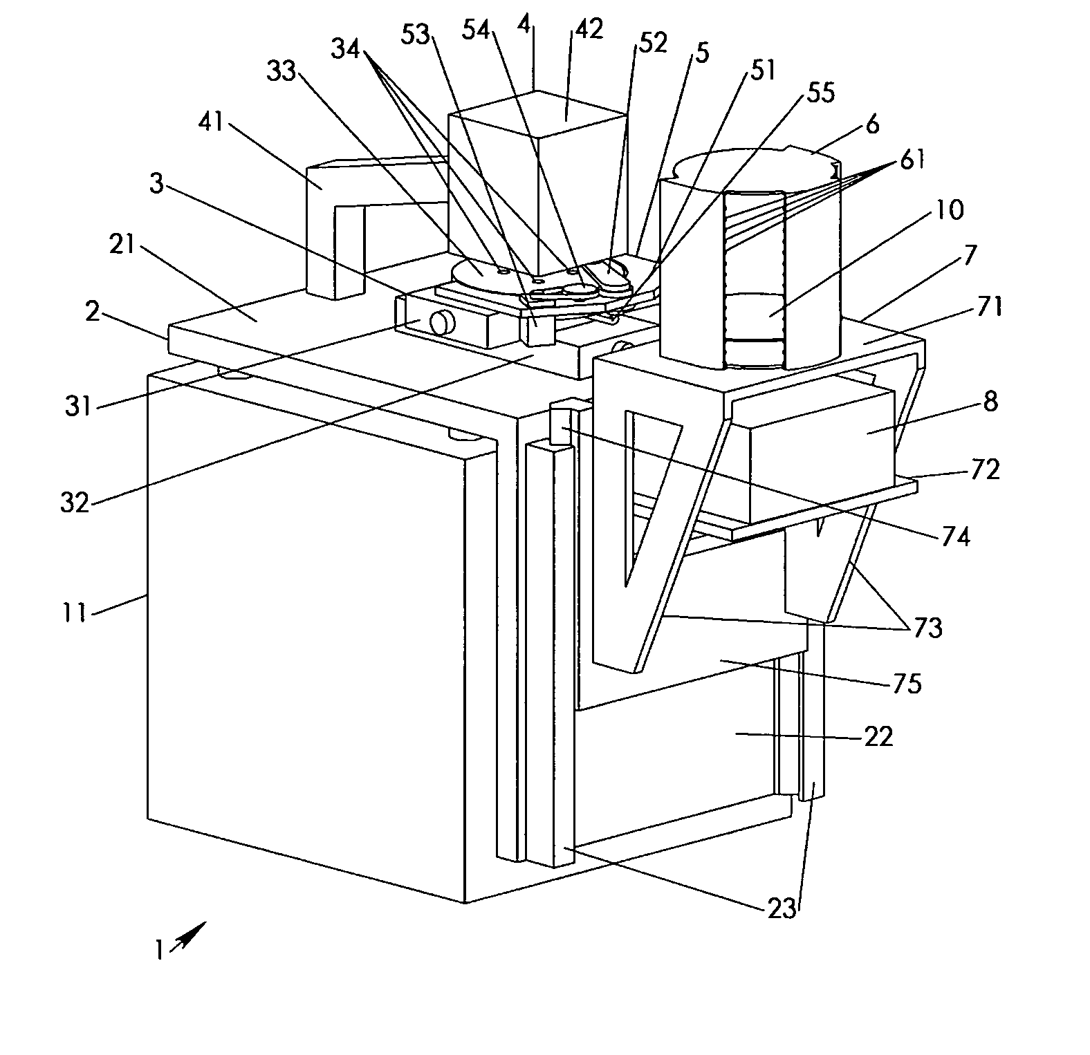
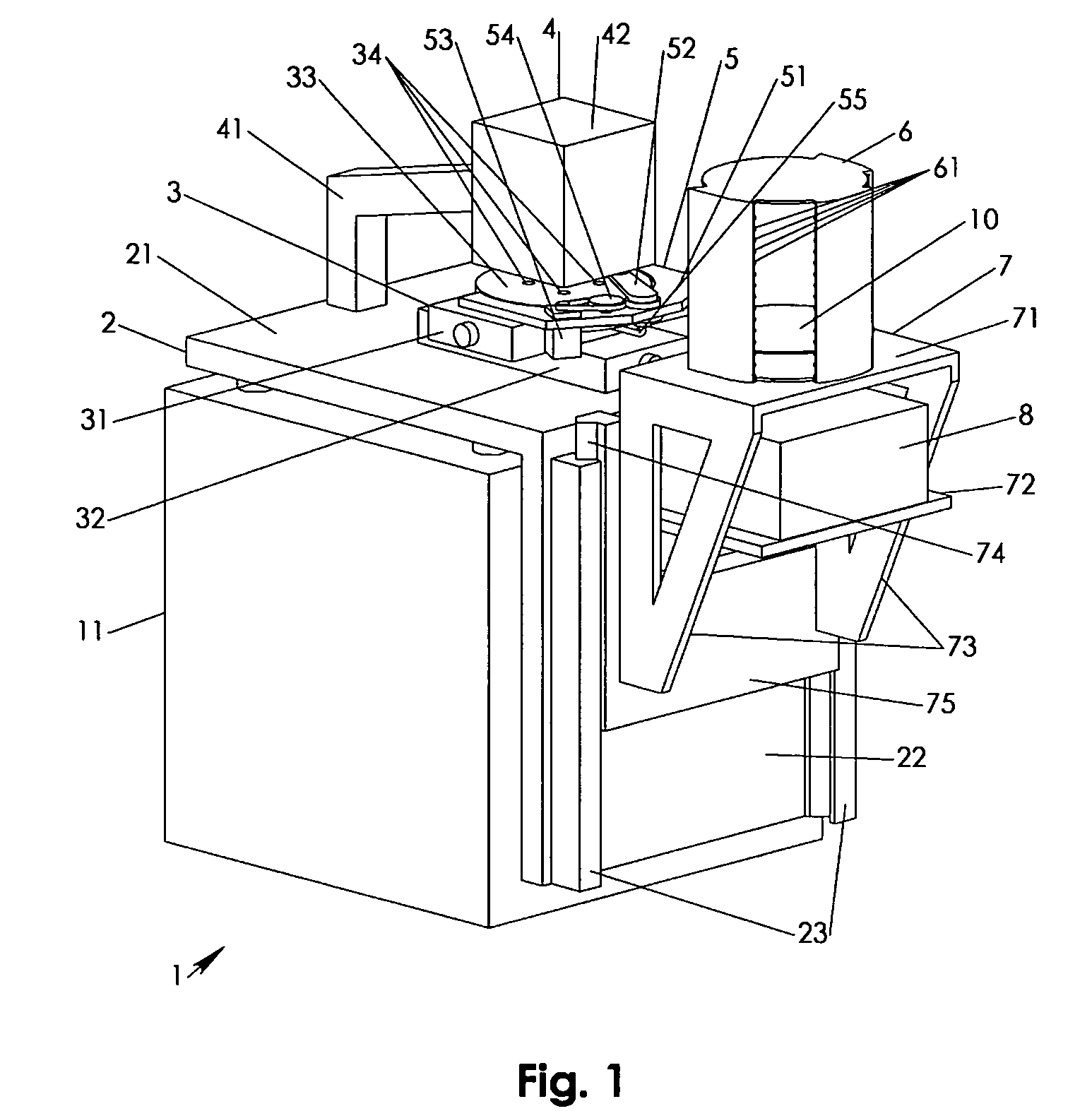
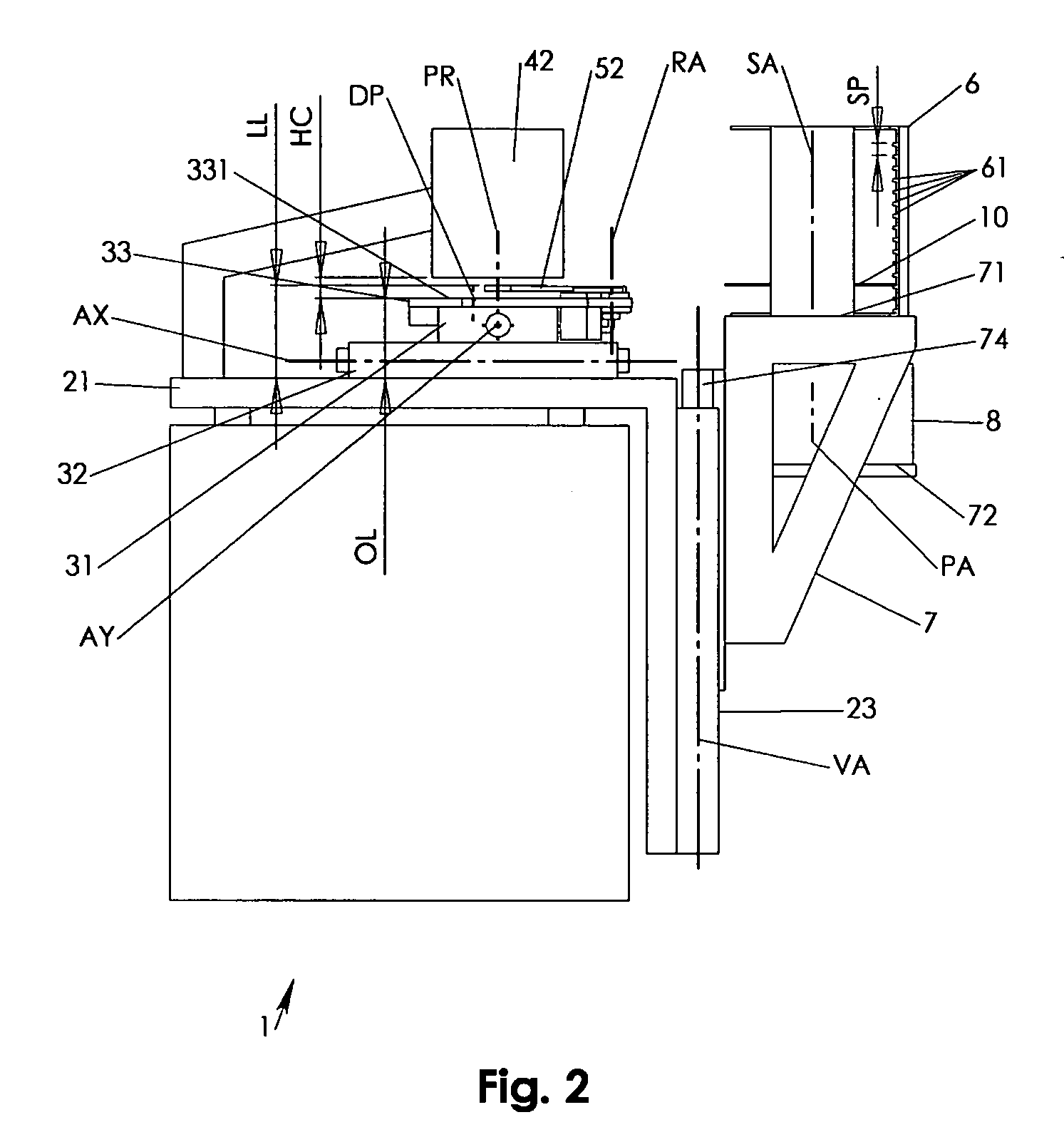
[0023] In accordance to FIG. 1, a wafer testing device 1 may be a well known spectrometer, reflectometer or other well known wafer testing device in which a wafer 10 needs to be moved and positioned with high precision. beneath and relative to a measurement head 42. In the Figures, the wafer 10 is a representation of a multitude of wafers that may be handled during operational use of the wafer testing device 1. Hence, where it is referred in the following to wafer 10 any single or multiple equally sized wafer(s) may be considered as appropriate and as it may well be appreciated by anyone skilled in the art.
[0024] The wafer testing device 1 may have a housing 11 combined with a base 2. The housing 11 may have any suitable configuration for providing structural support and for integrating additional well known components such as, for example, electrical and other supply devices, control computers and other devices that are well known parts of optical measurement devices.
[0025] The b...
PUM
 Abstract
Description
Claims
Application Information