Lightweight structure especially for an aircraft and method for making such a structure

a technology for aircraft and lightweight structures, applied in the field of aircraft construction, can solve the problems of low static strength characteristic of fiber reinforced laminates compared to monolithic materials, limited production of fiber reinforced laminates, and high cost of fiber reinforced laminate production, so as to increase the useful life of lightweight structures, reduce crack propagation, and reduce the effect of damage toleran

Active Publication Date: 2005-05-26
AIRBUS OPERATIONS GMBH
View PDF93 Cites 12 Cited by
  • Summary
  • Abstract
  • Description
  • Claims
  • Application Information

AI Technical Summary

Benefits of technology

[0014] The use of reinforcing layers according to the invention between an outer skin of metallic laminates and the ribs and / or stringers of a frame, as compared to an embodiment with an outer skin made of a monolithic sheet metal layer, has substantially reduced the propagation of cracks as long as the cracks do not get longer than approximately the spacing between two neighboring stringers. However, if the crack length approaches a length of about twice said spacing, the crack propagation reduction is more effective in a structure with an outer skin of a monolithic sheet metal material. Generally, the retardation of the crack propagation according to the invention can increase the useful life of a lightweight structure up to five times compared to conventional structures without an additional reinforcing layer between the outer skin and the stringers and / or ribs of the frame.
[0015] According to the invention not only the damage tolerance has been increased due to the retardation of the crack propagation, a weight reduction has also been achieved because it has been found that the use of the reinforcing layers between the outer skin and the ribs and / or stringers permits the use of thinner sheet metal layers for forming the outer skin. As a result the sheet metal thickness can be reduced up to 20% compared to conventionally used sheet metal thicknesses, thereby correspondingly reducing the total weight of the lightweight structure such as an aircraft body. This important advantage is particularly significant in connection with upper body shell sections of an aircraft body.

Problems solved by technology

However, presently fiber reinforced laminates have a lower static strength characteristic compared to monolithic materials.
As a result, a weight reduction of the lightweight structure is only possible in a few areas where the particular component is primarily designed with regard to damage tolerant characteristics rather than strength characteristics.
Furthermore, the production of fiber reinforced laminates is relatively expensive compared to the production of monolithic materials due to the, at least partially, complicated pretreatment required for the subsequent adhesive bonding operation and due to the use of additional prepreg films and the need for manually positioning and preparing the individual laminae for the subsequent adhesive bonding operation.
As a result, the production costs can be significantly higher than the production costs of monolithic sheet metals.

Method used


Image

  • Lightweight structure especially for an aircraft and method for making such a structure
  • Lightweight structure especially for an aircraft and method for making such a structure
  • Lightweight structure especially for an aircraft and method for making such a structure

Examples


Embodiment Construction

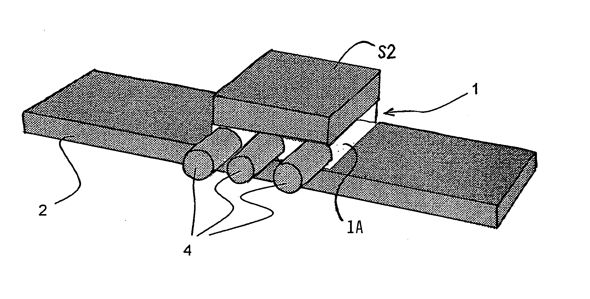
[0023]FIG. 6 shows a view onto a broken away section of an aircraft lightweight body structure including a frame or framework FW of ribs R1, R2, R3 extending circumferentially around the longitudinally aircraft axis while stringers S1, S2, S3 extend parallel to the longitudinal aircraft axis. The ribs and stringers are adhesively bonded to the inwardly facing surface of an outer skin 2. A plane extending perpendicularly to the plane of the sheet of the drawing and designated by arrows I-I illustrates the position of a reinforcing layer in the perspective view of FIG. 1 between the outer skin 2 and a stringer S2 in the framework FW. More specifically, the reinforcement layers according to the invention are positioned between the outer skin 2 and the ribs, or between the outer skin and the stringers or between the outer skin and the ribs and stringers.

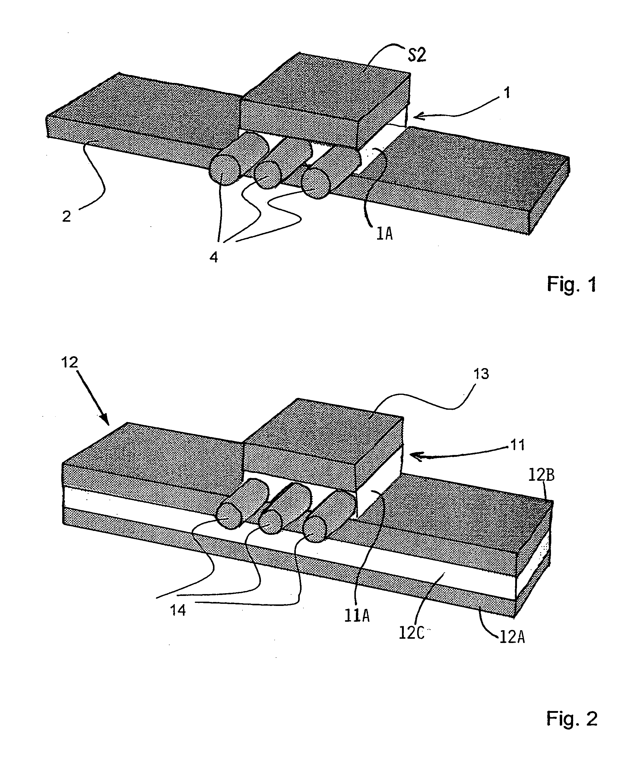
[0024]FIG. 1 shows a reinforcing layer 1 bonded by an adhesive matrix 1A to an outer skin 2 and to a stringer S2. The reinforcing laye...


PUM

PropertyMeasurementUnit
diameteraaaaaaaaaa
widthaaaaaaaaaa
lengthaaaaaaaaaa

Abstract

An additional fiber reinforced layer reduces crack propagation in a lightweight structure of an outer skin adhesively bonded to a reinforcing frame. For this purpose the additional fiber reinforced layer is interposed between the outer skin and the frame and adhesively bonded to the outer skin and to the frame. The additional layer has reinforcing fibers extending in parallel to each other or the reinforcing fibers are woven into a fabric embedded in a synthetic adhesive bonding material. The embedding of the parallel fibers or of the fiber fabric in the bonding material is performed either prior to the bonding or during the bonding of the additional layer to the outer skin and to the reinforcing frame.

Description

PRIORITY CLAIM [0001] This application is based on and claims the priority under 35 U.S.C. §119 of German Patent Application 103 30 708.7, filed on Jul. 8, 2003, the entire disclosure of which is incorporated herein by reference. FIELD OF THE INVENTION [0002] Lightweight structures are used primarily in aircraft construction, particularly aircraft bodies including an outer skin adhesively bonded to a framework. The invention also relates to a method for constructing such a lightweight structure by adhesive bonding. BACKGROUND INFORMATION [0003] Lightweight structures for use in the aircraft and spacecraft technologies include an outer skin which is strengthened on its inner surface by a reinforcement or stiffening framework. Such a framework is in fact a three dimensional structure but may be referred to as being “two-dimensional” to distinguish the framework from a three-dimensional aircraft or spacecraft body. An aircraft body, for example, is constructed as a lightweight structur...

Claims


Application Information

Patent Timeline
Patent Type & Authority Applications(United States)
IPC IPC(8): B32B15/08
CPCB32B15/08B32B3/14B32B7/12B32B15/02B32B15/20B32B2260/021B32B2262/0269B32B2262/10B32B2262/101B32B2262/106B32B2305/08B32B2311/18Y10T428/249924
Inventor SCHMIDT, HANS-JUERGENVICHNIAKOV, ALEXEI
Owner AIRBUS OPERATIONS GMBH
Why Eureka
Try Eureka