Method for efficiently processing DMA transactions

a dma transaction and efficient technology, applied in the field of general purpose computer systems, can solve the problems of inconsistencies in various versions, inability to provide partial cache coherency support for standard i/o devices, and inability to efficiently use the cpu bus, so as to increase the data rate of dma transactions and increase the data rate of certain dma transactions.

Inactive Publication Date: 2005-05-26
MILLER GEORGE B
View PDF5 Cites 49 Cited by
  • Summary
  • Abstract
  • Description
  • Claims
  • Application Information

AI Technical Summary

Benefits of technology

[0013] I have discovered that it is possible to significantly increase the data rate of DMA transactions between I/O devices and shared memory, without the need to modify the I/O device drivers, by disabling the system controller coherency protocol and programming the system controller to transmit the I/O request directly to the CPU bus. Further, I have discovered that it is possible to increase the data rate for cer

Problems solved by technology

However, standard I/O devices may provide only partial support for cache coherency functionality.
Although this is the highest bandwidth communications path between I/O and the shared memory, such non-coherent transactions may result in the creation of inconsistencies in the various versions of data stored at different locations in the computer system.
As a system controller's coherency functionality does not operate nearly as efficiently as the CPUs coherency functionality, processing DMA requests in the coherency mode takes much more time than processing the same DMA request in the non-coherent mode.
Therefore, it is not desirable to utilize the coherent mode of system controller operation to process DMA requests.
Unfortunately, standards-based I/O device drivers do not usually arrive from the manufacturer ready to support cache coherency for I/O-processor bus transactions that operate in a non-coherent manner, so typically it is necessary f

Method used


Image

  • Method for efficiently processing DMA transactions
  • Method for efficiently processing DMA transactions
  • Method for efficiently processing DMA transactions

Examples


Embodiment Construction

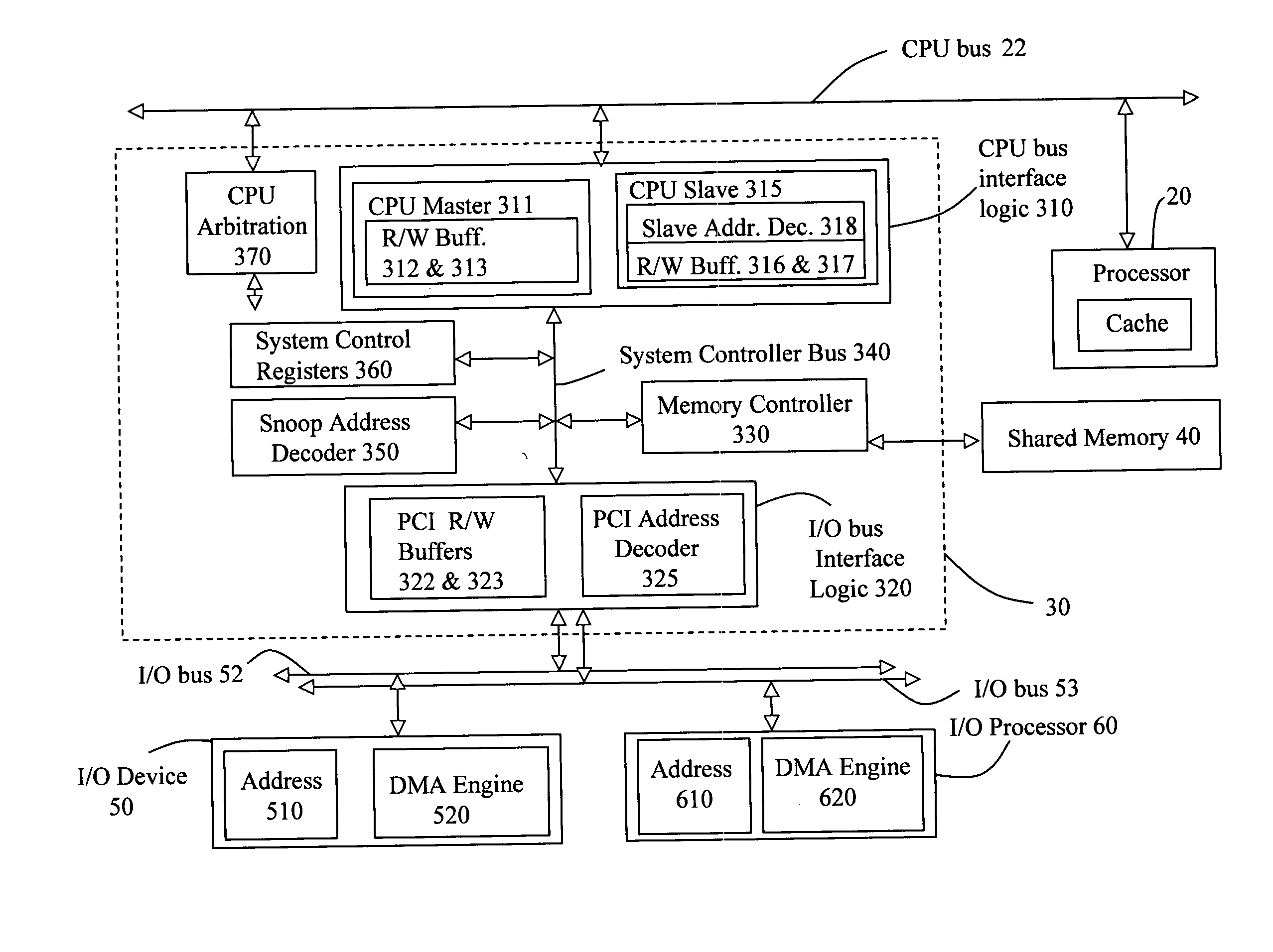
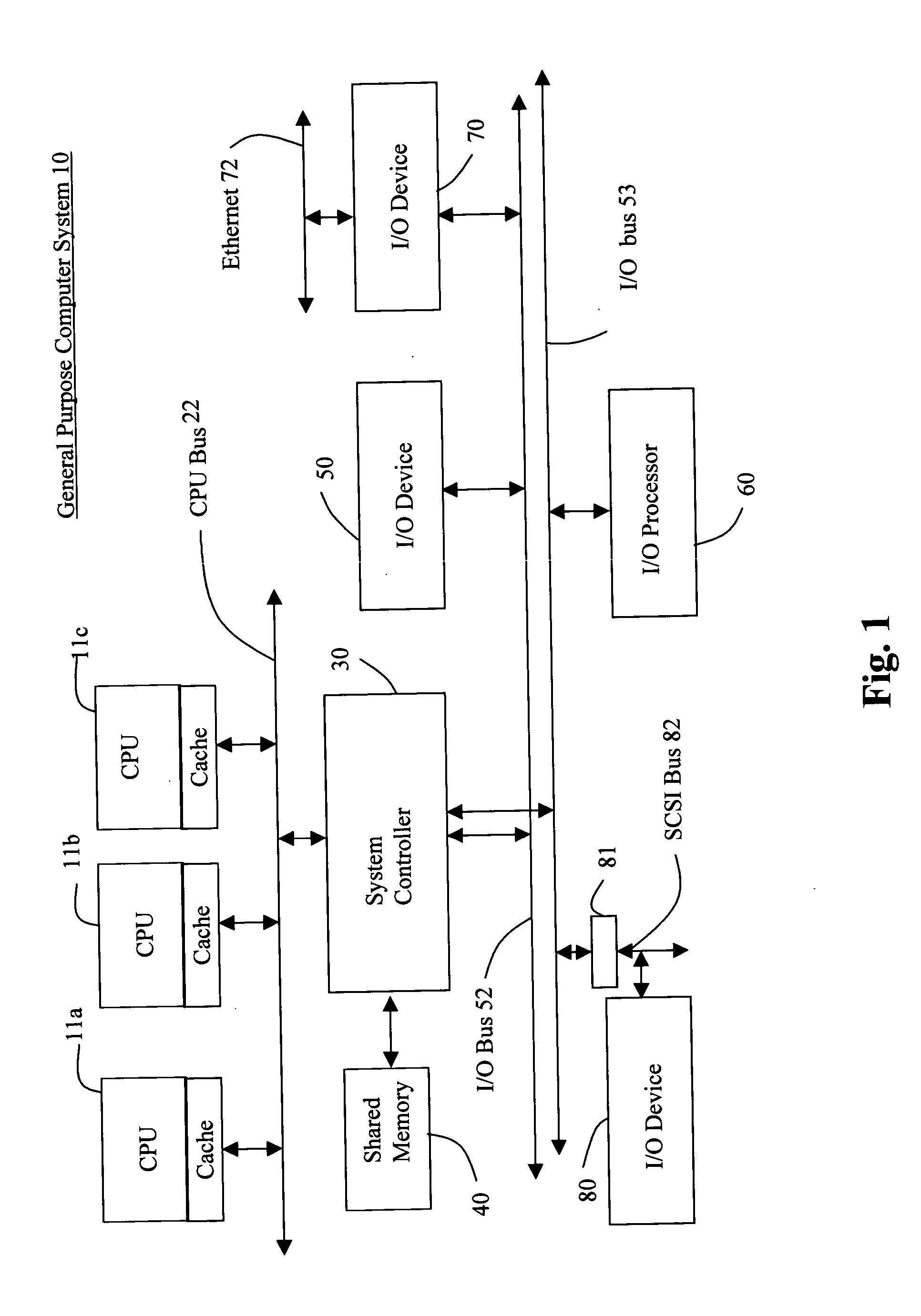
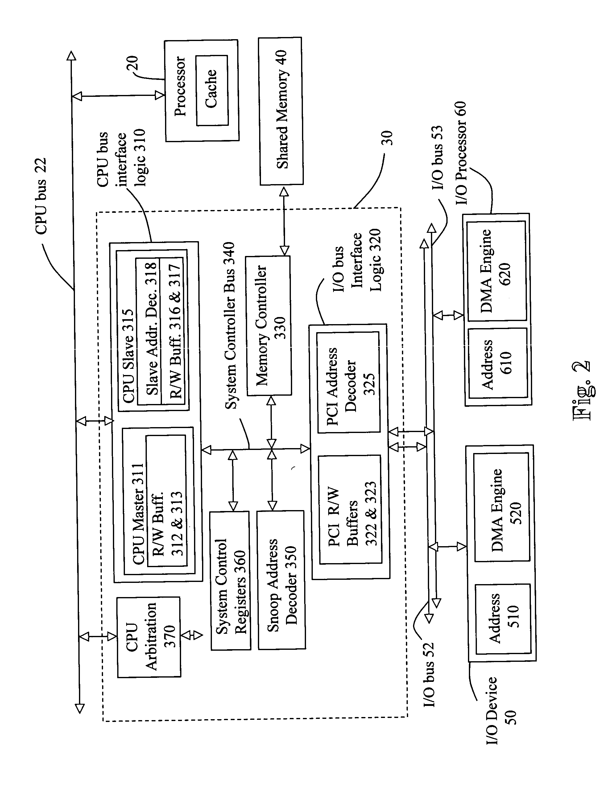
[0021]FIG. 1 is a high-level block diagram of a general-purpose computer system 10, hereinafter referred to as the computer system, which can be employed to implement the novel DMA transaction process described by this application. Such a computer system will typically have one or more central processing units (CPUs) 11a, b, and c, and associated cache memory in communication with a CPU bus 22. The CPU(s) enable much of the computer system's functionality. Among other things, they make and compare calculations, signal I / O devices to perform certain operations, and read and write information to memory. The cache associated with each CPU acts as a buffer, local to each CPU, for the storage of a version of data contained in the shared memory 40. Cache provides a mechanism for each CPU to very rapidly access a version of data that is contained in shared memory without using any CPU bus cycles. The CPU could be, for instance, a MPC7410 Power PC processor sold by the Motorola Corporation....


PUM


Abstract

The data rate at which DMA transactions are processed by a General Purpose Computer System can be significantly improved by directing housekeeping type transactions directly to the CPU bus and by directing data type transactions directly to Shared Memory. By assigning memory address ranges to particular I/O devices and by programming PCI Interface Logic on a System Controller to detect these ranges and to direct DMA requests directly to either the CPU bus or to the Memory Controller depending upon the address range detected, the speed with which DMA transactions can be processed is enhanced.

Description

BACKGROUND OF THE INVENTION [0001] Field of the Invention: This invention relates to the field of general purpose computer systems and to the efficient and coherent processing of DMA transactions between I / O devices and shared memory. BACKGROUND OF THE INVENTION [0002] General purpose computer systems are designed to support one or more central processors (CPUs) on a common CPU bus, one or more external I / O devices on one or more standard I / O buses, a shared system memory, and a system controller that serves as a communications interface between the CPU bus, the I / O bus, and the shared system memory. All of the CPUs and at least one, but typically most, of the I / O devices can communicate with the shared system memory. Cache memory has been incorporated into the CPUs of such computer systems in order to minimize the number of bus cycles or bandwidth needed to service transactions between the CPUs and the shared memory. This CPU cache architecture frees up bandwidth for other devices,...

Claims


Application Information

Patent Timeline
IPC IPC(8): G06F12/08G06F13/28
CPCG06F12/0835G06F13/28G06F12/0888
Inventor MILLER, GEORGE B.
Owner MILLER GEORGE B
Why Eureka
Try Eureka