Shoe that fits to a foot with belts

a technology of shoe and belt, applied in the field of shoes, can solve the problems of inability to support the foot in the vicinity of the distal caput of the fifth metatarsal bone of the foot, inability to obtain a sufficiently tight fit, and inability to use lace or belts

Active Publication Date: 2005-06-02
ASICS CORP
View PDF35 Cites 62 Cited by
  • Summary
  • Abstract
  • Description
  • Claims
  • Application Information

AI Technical Summary

Benefits of technology

[0037] In this case, since each double part of each belt in a loop shape passes through the slits and a loop parts of the belts engage with ...

Problems solved by technology

Such belts support the arch on the medial and lateral sides of the foot and its vicinity, but they cannot support the foot in the vicinity of the distal caput of the fifth metatarsal bone of the foot.
As such lace or belt stretches during wearing the shoe, a sufficiently tight fit cannot be obtained.
Moreover, such lace or belt cannot be used when the shoe has an inner upper covered with an outer upper.
However, a reinforcing member...

Method used


Image

  • Shoe that fits to a foot with belts
  • Shoe that fits to a foot with belts
  • Shoe that fits to a foot with belts

Examples


first embodiment

[0050]

[0051] A first embodiment of the present invention will be described below with reference to the figures.

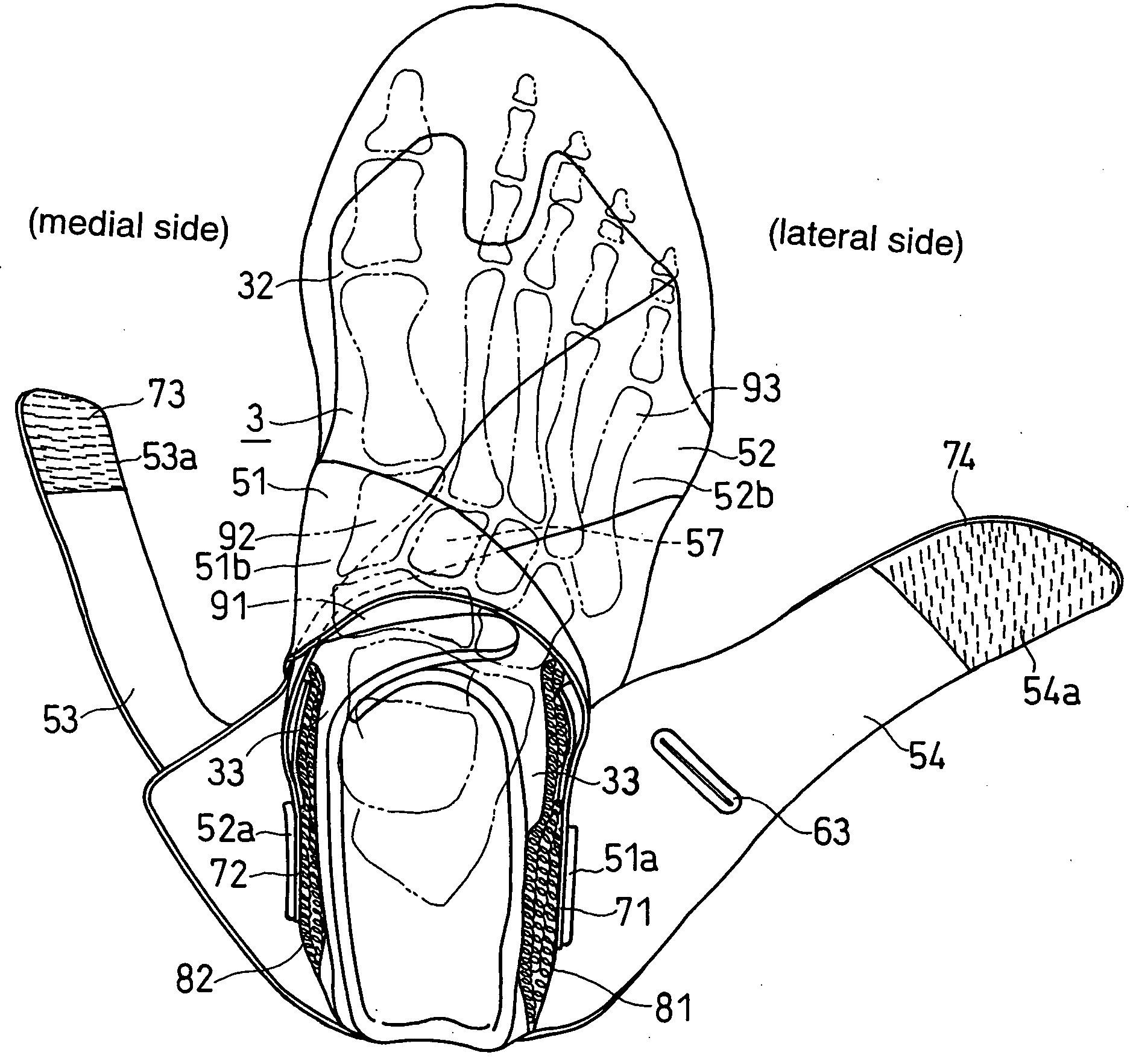
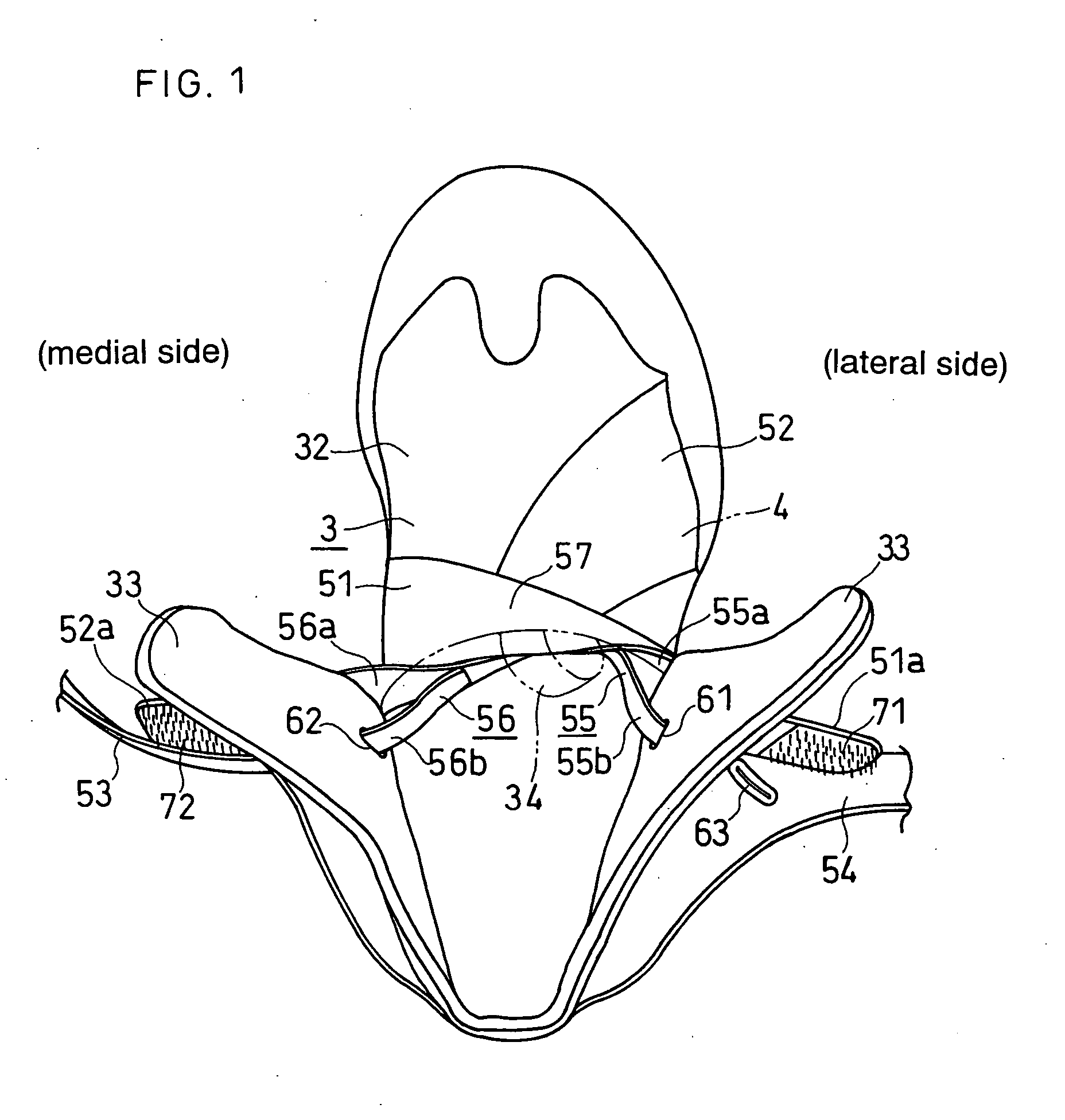
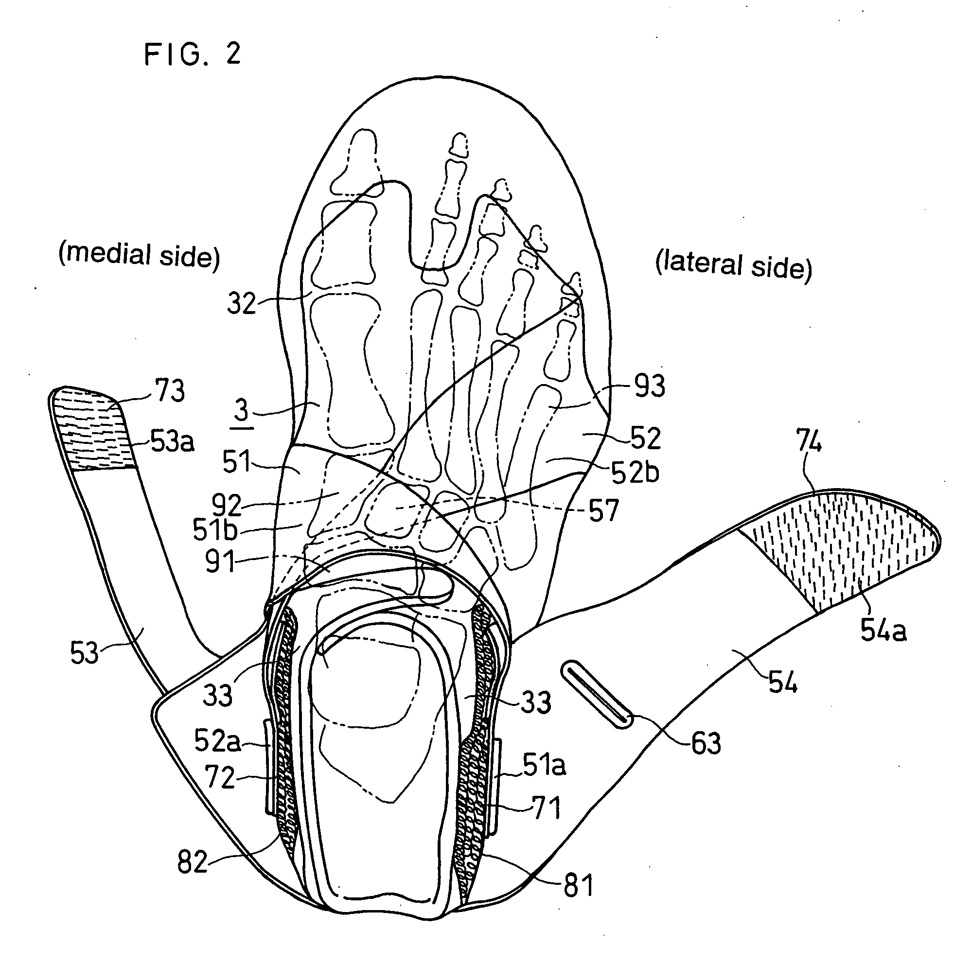
[0052]FIG. 1 to FIG. 7 show a first embodiment of a shoe for wrestling. FIG. 1 to FIG. 5 show a shoe for the right foot and FIG. 6 and FIG. 7 show a shoe for the left foot.

[0053] As shown in FIG. 1, the shoe of this embodiment has an inner upper 3, a sole S (FIG. 3), a first belt 51 and a second belt 52. As shown in FIG. 3 and FIG. 4, the sole S supports the sole of the foot and has a grounded portion (not shown) making contact with the floor or mat and first and second roll-up portions S11 and S10. As shown in FIG. 3, the first roll-up portion S11 rolls up from the grounded portion upwards along the medial side face of the foot. As shown in FIG. 4, the second roll-up portion S10 rolls up from the grounded portion upwards along the lateral side face of the foot. In FIG. 3 to FIG. 5, in order to easily understand the location of the first and second roll-up portions S11, S...

second embodiment

[0091]

[0092]FIG. 8 and FIG. 9 show a shoe (for the left foot) of a second embodiment. In the following description of this embodiment, the parts which are identical or corresponding to those of the first embodiment are designated by the same reference numerals as the first embodiment and the detailed description and illustration thereof will be omitted.

[0093] As shown in FIG. 8, in the shoe of this embodiment, the inner upper 3 extends above the ankle to form a substantially cylindrical folding portion 35. The folding portion 35 is split to the medial and lateral sides ahead of the ankle. The folding portion 35 is made of a flexible material having stretching property and can be folded with ease.

[0094] When putting on the shoe, the foot is inserted into the shoe from the folding portion 35 and then the folding portion 35 is folded back after fastening of the first and second belts 51, 52. As a result, as shown in FIG. 9, the folding portion 35 covers the secured portions 51a, 52a ...


PUM


Abstract

A shoe with belts according to the present invention comprising an upper, a sole S that has a first and second roll-up portions S11, S10 rolling upwards along side faces of a foot, and first and second belts 51, 52. The first belt 51 is fixed to the first roll-up portion S11 at a first joined portion 58 on the medial side of the foot. The second belt 52 is fixed to the second roll-up portion S10 at a second joined portion 59 on the lateral side of the foot. The pair of belts 51, 52 cross each other at a position approximately above the navicular bone 91. The first belt 51 can be arranged in a tensioned state along a path extending from the medial side of the foot to the vicinity of an ankle on the lateral side of the foot through the crossing position 57. The second belt 52 can be arranged in a tensioned state along a path extending from the lateral side to the vicinity of the ankle on the medial side of the foot through the crossing position 57.

Description

CROSS-REFERENCE TO RELATED APPLICATIONS [0001] The present application claims the benefit of patent application number 2003-398497, filed in Japan on Nov. 28, 2003, the subject matter of which is hereby incorporated herein by reference. BACKGROUND OF THE INVENTION [0002] 1. Field of the Invention [0003] The present invention relates to a shoe having improved fitting properties. [0004] The present invention can apply to various kinds of shoes such as wrestling shoes and tennis shoes. The present invention is useful especially for fastening shoes without shoe laces to the foot. [0005] 2. Description of the Related Art [0006] Shoes, for example for wrestling or tennis, having an inner upper covered with an outer upper, are known. [0007] These type of shoes require that the inner upper can be easily fastened to the foot. On the other hand, because there are many movements of the foot in the widthwise direction when the player is doing the above mentioned sports, it is necessary to make ...

Claims


Application Information

Patent Timeline
IPC IPC(8): A43B5/00A43B23/02A43B7/20A43C11/00
CPCA43B7/20A43B5/00A43C11/1493
Inventor YAMASHITA, YOSHIOMORIKAWA, YASUHIROLU, JHON
Owner ASICS CORP
Why Eureka
Try Eureka