Fast warm up pulse tube

Inactive Publication Date: 2005-06-02
SHI APD CRYOGENICS +1
View PDF10 Cites 18 Cited by
  • Summary
  • Abstract
  • Description
  • Claims
  • Application Information

AI Technical Summary

Benefits of technology

[0010] In one embodiment of the invention, a split rotary valve illustrates a si

Problems solved by technology

Not all pulse tube phase shifting mechanisms lend the

Method used


Image

  • Fast warm up pulse tube
  • Fast warm up pulse tube
  • Fast warm up pulse tube

Examples


Embodiment Construction

[0021] The present invention is applicable to G-M type pulse tubes that use valves to control the phase relationship of the flow to the warm end of the regenerator relative to the flow to the warm end of the pulse tube. By changing the phase relationship, the pulse tube can be made to shift from a cooling mode to a warming mode.

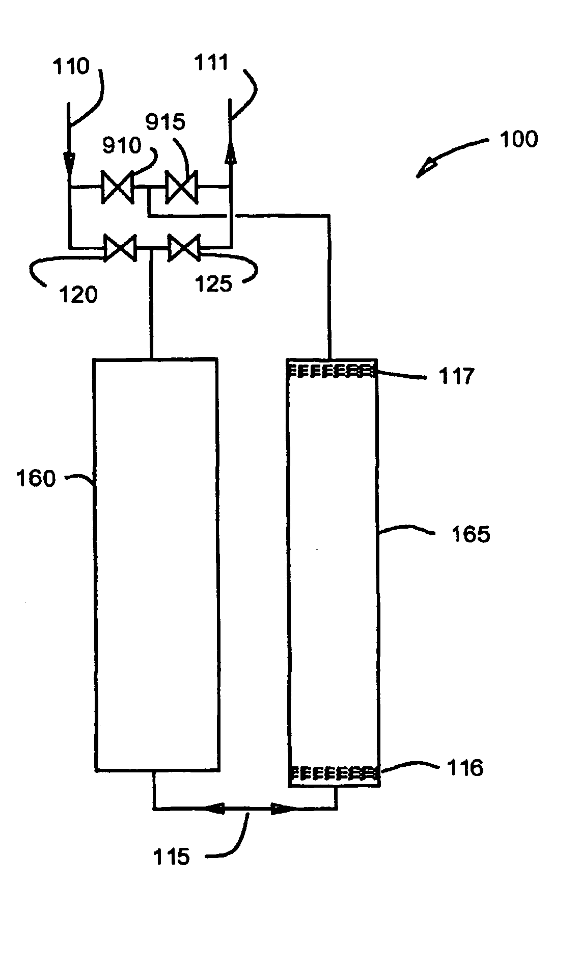
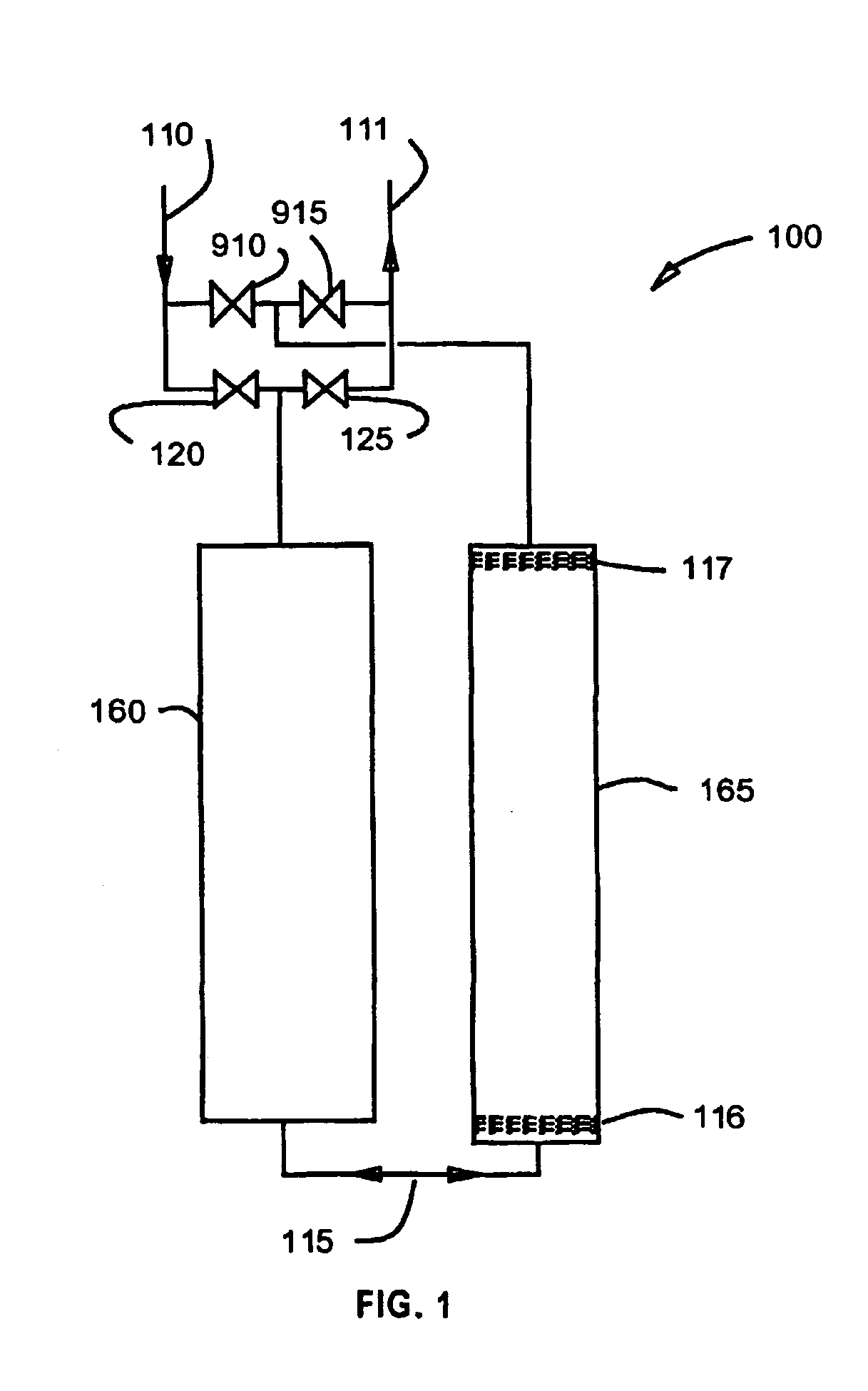
[0022] The single stage pulse tube shown in FIG. 1 illustrates an embodiment of the invention. FIG. 1 shows Pulse Tube Refrigerator 100, which is comprised of Regenerator 160, Pulse Tube 165, Connecting Tube 115. Gas Line 110, Gas Line 111, Valve 120, Valve 125, Valve 910, Valve 915, Cold Heat Station 116, and Hot Heat Station 117.

[0023] Gas Line 110 brings high-pressure gas from the compressor and Gas Line 111 returns gas at low pressure to the compressor. Valve 120 admits high-pressure gas to the warm end of Regenerator 160 and Valve 125 returns gas from the warm end of Regenerator 160 to the compressor. Valve 910 admits high-pressure gas to the warm end ...


PUM


Abstract

This invention provides an improved means of quickly warming a pulse tube (165) by shifting the phase relation of flow to the warm end of the pulse tube relative to flow to the warm end (117) of the pulse tube relative to flow to the warm end of the regenerator (160) using a “four valve” concept and the “active buffer” concept. Several different pulse tube configurations and valve timing relations that are effective at reversing the cycle from the normal mode, which produces cooling at the pulse tube heat station, to a reverse mode that produces heating are disclosed.

Description

BACKGROUND OF THE INVENTION [0001] The Gifford-McMahon (G-M) type pulse tube refrigerator is a cryocooler, similar to G-M refrigerators, that derives cooling from the compression and expansion of gas. However, unlike the G-M systems, in which the gas expansion work is transferred out of the expansion space by a solid expansion piston or displacer, pulse tube refrigerators have no moving parts in their cold end, but rather an oscillating gas column within the pulse tube that functions as a compressible displacer. The elimination of moving parts in the cold end of pulse tube refrigerators allows a significant reduction of vibration, as well as greater reliability and lifetime, and is thus potentially very useful in cooling cryopumps, which are often used to purge gases from semiconductor fabrication vacuum chambers. [0002] G-M type pulse tube refrigerators are characterized by having a compressor that is connected to a remote expander by high and low pressure gas lines. The pulse tube...

Claims


Application Information

Patent Timeline
IPC IPC(8): F25B9/14F25B45/00
CPCF25B9/145F25B45/00F25B2309/006F25B2309/14241F25B2309/1411F25B2309/1418F25B2309/14181F25B2309/1408
Inventor GAO, JIN LINLONGSWORTH, RALPH C.
Owner SHI APD CRYOGENICS
Why Eureka
Try Eureka