
Martensitic stainless steel seamless pipe and a manufacturing method thereof

Active Publication Date: 2005-06-02
NIPPON STEEL CORP
View PDF4 Cites 1 Cited by
  • Summary
  • Abstract
  • Description
  • Claims
  • Application Information

AI Technical Summary

Benefits of technology

[0006] It is the primary objective of the present invention to provide a martensitic stainless steel pipe, containing C of about 0.2%, which suppresses a delayed fracture in the impact-worked portions before a heat treatment after rolling, and also generates no internal scab.
[0007] It is a second objective of the present invention to provide a method for manufacturing a martensitic stainless steel pipe, without an internal scab generation, which suppresses a delayed fracture in the impact-worked portions before a heat treatment after rolling.

Problems solved by technology

Consequently, an as rolled conventional martensitic stainless steel pipe might have a crack resulting from a delayed fracture in “the impact-worked portion”, where an impact load or static load was worked before a heat treatment.
The above-mentioned restrictions during transportation or storage could result in various disadvantages such as a large stockyard because of the restriction of the piling height and / or the dropping height of pipes, a reduction in working efficiency resulting from the careful handling of the steel pipes without excessive loading impact and a restricted time schedule from hot rolling to a heat treatment in order to finish the heat treatment within a restricted working period.
However, neither the relationship between the N content and a delayed fracture in the impact-worked portions of an as-rolled steel pipe nor the measures for suppressing such inner surface defects as internal scabs due to poor hot workability resulting from the decreased N content is described.
It is not practical to manufacture a seamless steel pipe without any measures to suppress internal scabs.

Method used


Image

  • Martensitic stainless steel seamless pipe and a manufacturing method thereof
  • Martensitic stainless steel seamless pipe and a manufacturing method thereof
  • Martensitic stainless steel seamless pipe and a manufacturing method thereof

Examples


examples

[0077] Seamless pipes, having a 60.3 mm outer diameter and a 4.83 mm thickness, were produced from 43 kinds of steel having the chemical composition shown in Tables 1 and 2. Then the following tests were carried out for these steel pipes.

(1) Delayed Fracture Test

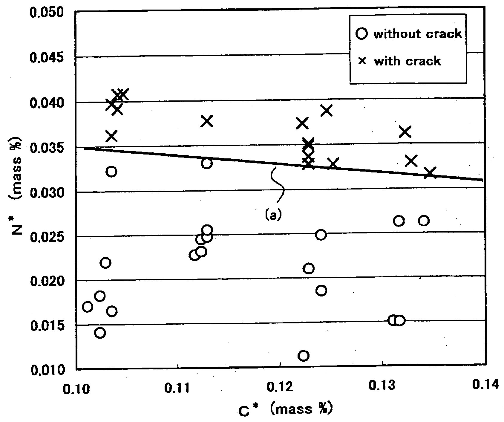
[0078] Drop test pieces having a 250 mm length were prepared from as-rolled steel pipes. A weight test element, having 150 kg weight and a 90 mm curvature at its tip, was dropped from a 0.2 m height onto a test piece, which is deformed under an impact load (294J). After one week each piece was inspected as to whether or not cracks were generated. An inspection of cracks was carried out by a visual check and also by an ultrasonic test (UST). The results are listed in Tables 3 and 4.

[0079]FIG. 1 is a diagram showing the relationship between the generated cracks and both effective solute carbon content (C*) and effective solute nitrogen content (N*). As shown in the diagram, a straight line “a” implies a boundary of generat...


PUM

PropertyMeasurementUnit
Temperatureaaaaaaaaaa
Fractionaaaaaaaaaa
Fractionaaaaaaaaaa

Abstract

The present invention provides a martensitic stainless steel seamless pipe, having no inner surface defect and suppressing a delayed fracture generation in the impact-worked portions, and a method for manufacturing such a seamless steel pipe. A martensitic stainless steel seamless pipe, characterized by consisting of C: 0.15 to 0.22%, Si: 0.1 to 1.0%, Mn: 0.10 to 1.00%, Cr: 12.00 to 14.00%, P: 0.020% or less, S: 0.010% or less, N: 0.05% or less, O (Oxygen): 0.0060% or less, at least one alloying element selected from V, Nb and Ti of 0.005 to 0.200% and B of 0.0005 to 0.0100%, and the balance Fe and impurities, satisfying either the following inequalities (1), (2), (4) and (5) or the following inequalities (1), (3), (4) and (5): C*+10N*≦0.45,  (1) H1≦−0.003(C*+10N*)+0.0016,  (2) H2≦−0.0018(C*+10N*)+0.00096,  (3) Cr*≦9.0,  (4) S≦0.088N*+0.00056,  (5)

Description

TECHNICAL FIELD [0001] The present invention relates to a martensitic stainless steel seamless pipe, such as a pipe for an oil well, which ensures no generation of cracks resulting from a delayed fracture. The present invention also relates to a method for manufacturing such a martensitic stainless steel pipe without any generation of inner surface defects such as internal scabs. BACKGROUND ART [0002] A martensitic stainless steel such as API-13% Cr, which is used as a pipe for an oil well, normally includes a carbon content of about 0.2%, which needs a high yield strength of 80 ksi (552 MPa) or more and a hot workability. Due to a high C and Cr content, an as-rolled stainless steel pipe has an extreme hardness, therefore has a reduced toughness. Consequently, an as rolled conventional martensitic stainless steel pipe might have a crack resulting from a delayed fracture in “the impact-worked portion”, where an impact load or static load was worked before a heat treatment. Accordingl...

Claims


Application Information

Patent Timeline
IPC IPC(8): C21D8/10C21D9/08C22C38/26C22C38/28
CPCC21D6/002C21D8/105C21D9/08C21D2211/008C22C38/46C22C38/02C22C38/04C22C38/42C22C38/004
Inventor KIDANI, SHIGERUTANIDA, MUTSUMI
Owner NIPPON STEEL CORP
Features
  • Generate Ideas
  • Intellectual Property
  • Life Sciences
  • Materials
  • Tech Scout
  • Unparalleled Data Quality
  • Higher Quality Content
  • 60% Fewer Hallucinations
Learn More