
Manually actuated brake system for manually towable vehicle

a brake system and manual action technology, applied in the direction of braking systems, automatic initiation, transportation and packaging, etc., can solve the problems of large force necessary to apply sufficient braking resistance, and inability to provide safety mechanisms for hydraulically assisted mechanisms. to achieve the effect of facilitating the movement of the trailer

Active Publication Date: 2005-06-02
SNAP ON INC
View PDF33 Cites 19 Cited by
  • Summary
  • Abstract
  • Description
  • Claims
  • Application Information

AI Technical Summary

Benefits of technology

[0007] A brake control cable is disposed along the length of the trailer with one terminus adjacent to the brake assembly and coupled to the brake actuation lever, and the opposite terminus coupled to cam plates integrally disposed with the pivotal handle. The handle is pivotally coupled to the front end of the trailer and can pivot from first and second positions, relative to the trailer, via a handle swivel assembly, whereby the vertical pivotal orientation controls brake application and the horizontal pivotal orientation controls steering. Movement from either the first or second position causes the brake assembly to be released, thus facilitating movement of the trailer. A camming structure disposed in the cam plates selectively applies a generally forwardly directed pulling force to the cable based upon the relative vertical pivotal orientation of the handle, thus causing the braking assembly to release the brakes. Due to the handle's pivotal lever design, minimal user force is required at the distal end of the handle to dispose the handle in the necessary inclined angle, relative to the trailer, to release the brakes. The handle also ensures that if the handle is in a substantially vertical orientation, such as when the trailer is stowed, or in a substantially horizontal position, such as when the handle is dropped, the brakes are immediately applied, thus providing requisite braking safety.

Problems solved by technology

However, due to these trailers' large size and heavy mass, the force necessary to apply sufficient braking resistance may be great, and generally much greater than can be supplied by a typical user's manual force exertion upon the lever.
A limitation of such a braking mechanism is that such hydraulic assistance requires a complex and costly sub-assembly of hydraulic actuators, piping, fluid, and the like, all of which require frequent maintenance.
Further, such a hydraulically assisted mechanism does not provide any safety mechanisms if, for example, the trailer runs out of control while descending a ramp or while the trailer is stowed.

Method used


Image

  • Manually actuated brake system for manually towable vehicle
  • Manually actuated brake system for manually towable vehicle
  • Manually actuated brake system for manually towable vehicle

Examples


Embodiment Construction

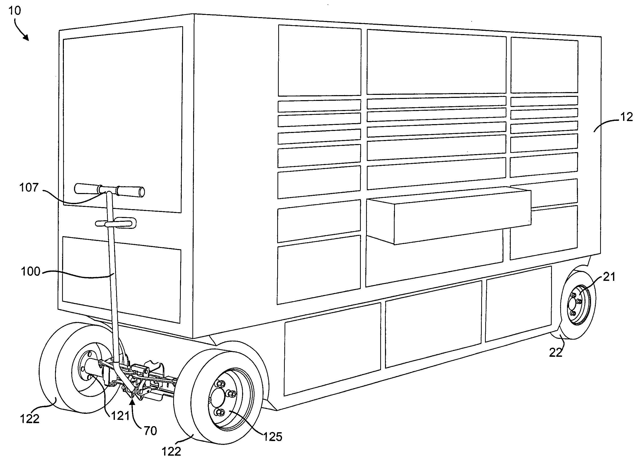
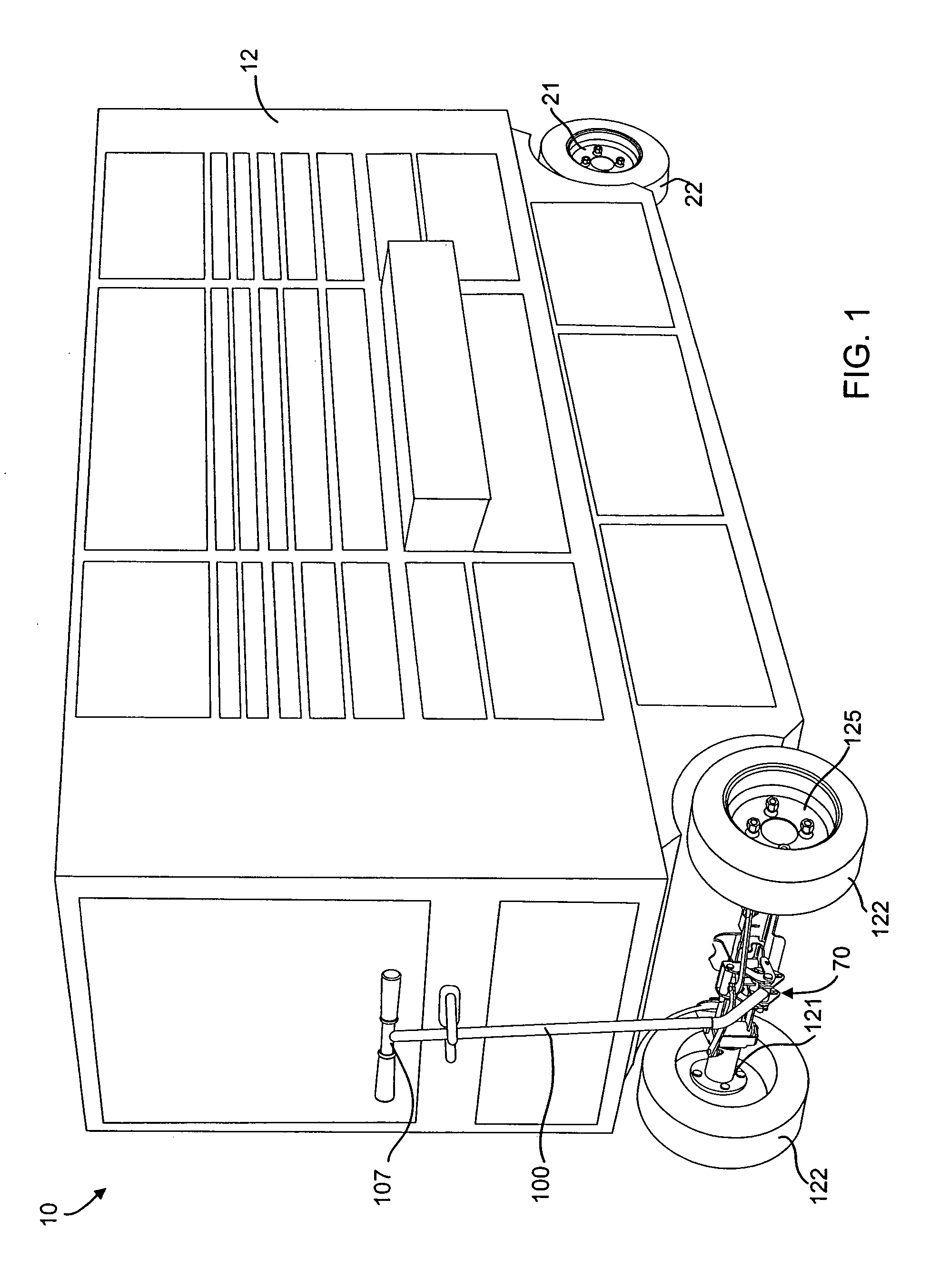
[0021] The present application discloses a manually operated mechanical braking apparatus and method for a hand maneuverable wheeled vehicle, such as a tool carrying and storage trailer, which is easily operated by manual manipulation of the orientation of a vertically pivotal handle disposed on the front end of the trailer. While a tool carrying and storage trailer is depicted in the figures, it will be appreciated that the invention described herein can be used with any type of hand operated vehicle and that the depiction of a tool trailer is used for illustrative purposes only.

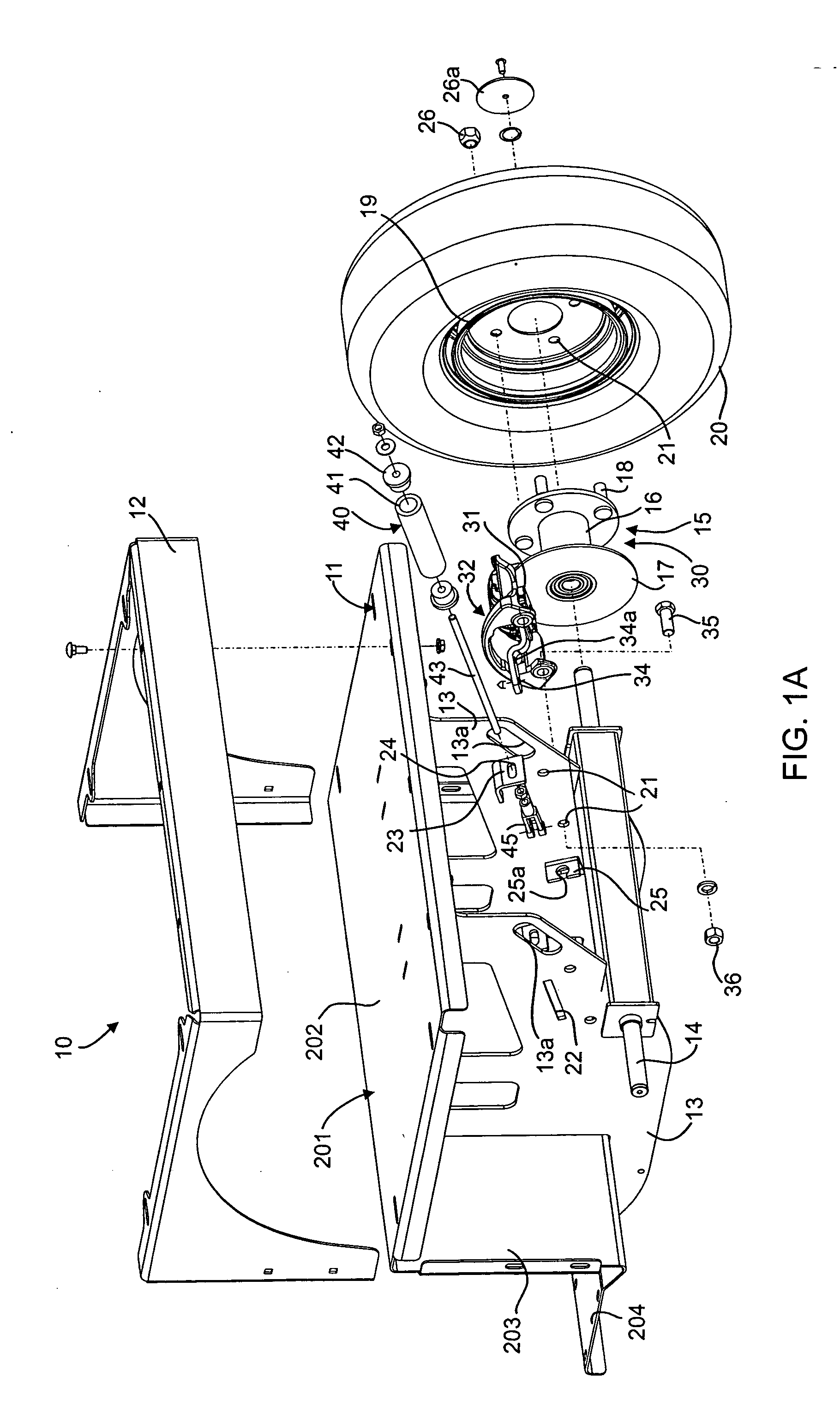
[0022] Referring to FIGS. 1 and 1a, a tool storage trailer 10 is shown including a body 12 and a frame 11 supporting a transversely disposed rear axle 14. A wheel hub 15 having a cylindrical body 16 adapted for rotatably receiving therein an end of the axle 14 includes a braking assembly 30 having an annular brake rotor 17 sandwichingly disposed between inner and outer brake pads 31 that are operably coupl...


PUM


Abstract

A brake system for a vehicle having a plurality of wheels and a frame comprising a mechanically actuated braking assembly operably coupled with at least one of the wheels and being operable between braking and non-braking conditions, a handle coupled to the braking assembly and being mounted to the frame for pivotal movement about a substantially horizontal axis between first and second positions in each of which the braking assembly is in the braking condition, and an actuating mechanism responsive to movement of the handle from either of the first and second positions for actuating the braking assembly into the non-braking condition.

Description

CROSS REFERENCE TO RELATED APPLICATION [0001] The present application claims the benefit of the filing date of co-pending U.S. Provisional Application No. 60 / 465,323, filed Apr. 25, 2003.BACKGROUND OF THE INVENTION [0002] The present application relates generally to brake systems for hand operated vehicles and more particularly to mechanically actuated brake systems for hand operated wheeled vehicles. [0003] Hand operated tool “trailers” are wheeled vehicles including a large, heavy and cumbersome item, such as a tool cabinet or chest, with wheels and a towing handle attached. Thus, such trailers typically require some type of reliable braking system. This is typically accomplished by disposing a handle at the front end of the trailer that is used for pushing, pulling and steering the trailer, and placing a hand operated braking lever adjacent to the handle that is operatively coupled to a braking mechanism associated with at least one of the wheels. The lever is typically actuated ...

Claims


Application Information

Patent Timeline
IPC IPC(8): B60TB60T7/08B60T7/10B60T11/04B60T17/18B62B5/04
CPCB60T7/102B60T17/18B62B3/002B62B5/0442B62B5/04B62B5/048B62B5/0438B62B5/0083B60T7/08B62B2005/0471
Inventor DOERFLINGER, DAVID A.GUPTAIL, DANIEL
Owner SNAP ON INC
Learn More