
Dragless flight control system for flying objects

a flight control and flying object technology, applied in the direction of airflow influencers, weapons, transportation and packaging, etc., can solve the problems of large control force of canard control, major limitations of this type of control, and consequential limited control authority, so as to reduce the total power loss and minimize drag

Inactive Publication Date: 2005-06-02
UNITED STATES OF AMERICA THE AS REPRESENTED BY THE SEC OF THE ARMY
View PDF9 Cites 22 Cited by
  • Summary
  • Abstract
  • Description
  • Claims
  • Application Information

AI Technical Summary

Benefits of technology

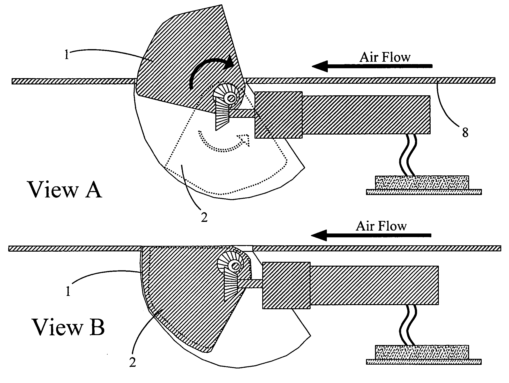
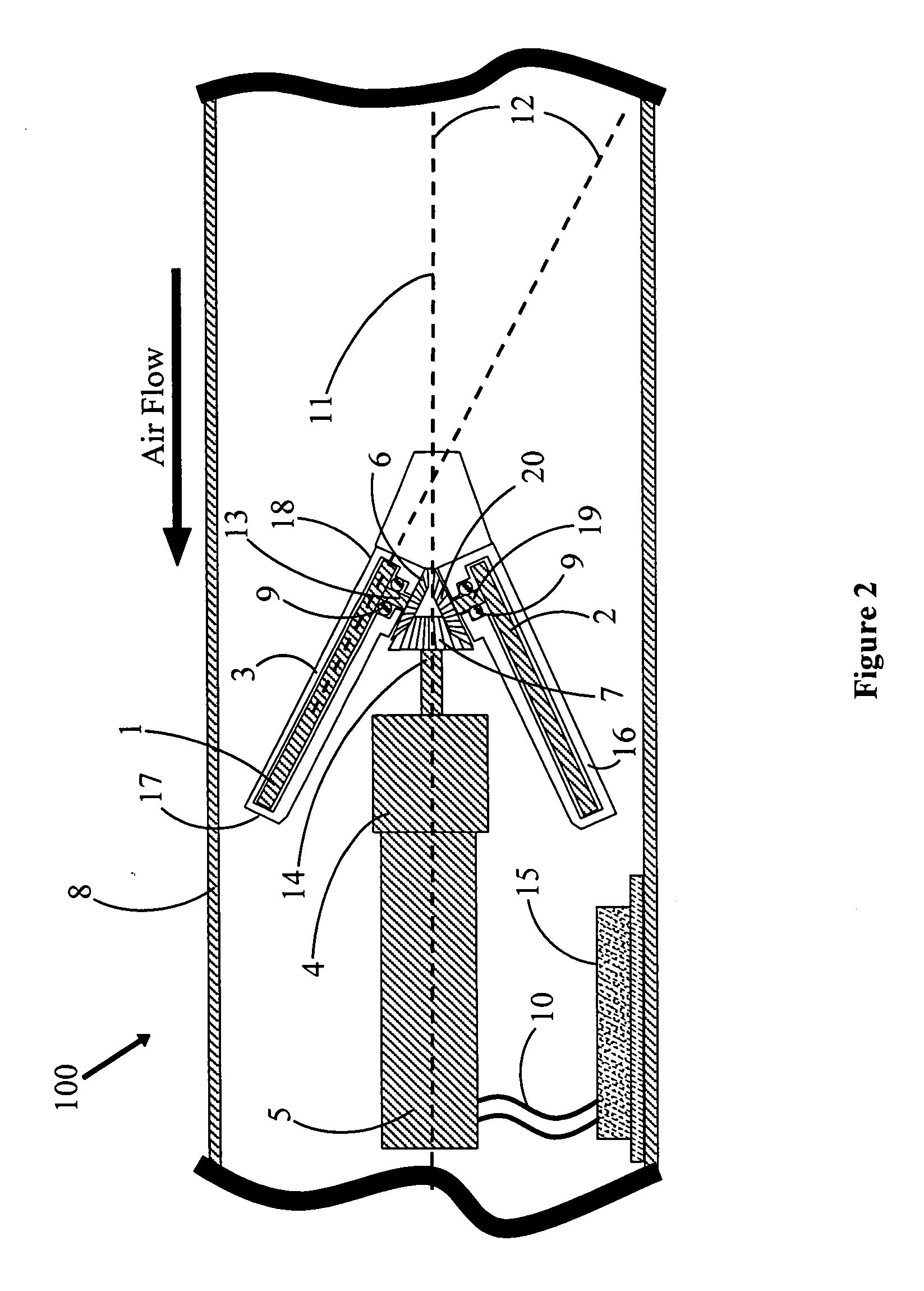
[0004] The Dragless Flight Control System for Flying Objects, referred to as the DFCS, greatly minimizes drag and, as a result, reduces the total power loss suffered by the object during its flight. With the DFCS, drag exists only when the fins are proportionally extended for control purposes. When the object is set on its flying course, the fins are retracted completely into the body of the object, thus offering no resistance. Thus, the drag force exerted during the typical period that the fins are extended for control purposes is a mere fraction of the maximal drag force exerted by the permanently extended fins.
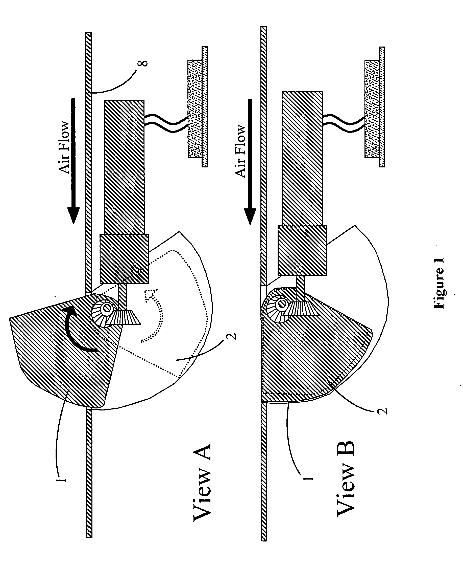
[0005] In DFCS, the retractable fins are mounted in pairs and are set to maximum no-stall angle 12 relative to axis 11 of flying object 100, the maximum angle being dependent on the operational speeds and the desired control characteristics of the particular object. The maximum angle is chosen to provide maximum lift over the range of the object's speeds while avoiding the loss of lift due to the stalling of the fin. The fins are selectively exposable outside exterior skin 8 of the flying object by being rotated on their axes, the two fins of a pair always being rotated by the same rotation angle but in opposite directions. The degree of fin exposure is determined by the degree of rotation angle, the rotation angle being changeable to vary the portion of the fin being exposed. Varying the exposed area of the counter-rotating fins can generate lift effect that is proportional to the exposed area and similar to that produced by the current extended standard rotational fins. When no lift force is needed, the fins retract into a position flush with the exterior skin of the flying object, thus offering no drag.

Problems solved by technology

Such standard rotational canard control generates large control forces because of the “lift” generated by angling the canards to a desired angle into the air flowing around the missile body during missile flight.
But major limitations attend this type of control.
The most substantial are the canard drag forces and the consequential limited control authority afforded during the boost phase of the missile.
The drag added by the rigidly extended canards impacts the overall missile design, especially for those missiles required to carry large propellant loads because of the range to be covered.
The currently-used extended-canard configuration severely reduces the missile range as well as speed.

Method used


Image

  • Dragless flight control system for flying objects
  • Dragless flight control system for flying objects
  • Dragless flight control system for flying objects

Examples


Embodiment Construction

[0012] Referring now to the drawing wherein like numbers represent like parts in each of the several figures, the structure and operation of the DFCS is explained.

[0013] A typical flying object in which the DFCS may be employed is missile 100 having body axis 11 that is parallel with the length of the missile and a guidance computer (which may or may not be integral with controller 15) that, as a part of its guidance function, issues command signals for the desired rotational positions of fins 1 and 2. The two fins of a pair are mounted to rest in their respective housings 3 and 16 that are positioned to be on the same side of missile body axis 11. The housings are mirrored on that side with axis 11 between them and are recessed into the body of the missile. Each of the fins has front end 18 and back end 17. In the preferred embodiment of DFCS as depicted in FIG. 2, the front ends of the fins are closer together than the back ends of the fins. When no lift effect is desired for the...


PUM


Abstract

The Dragless Flight Control System for Flying Objects utilizes paired fins that are mounted to rotate in opposite directions. When no lift is desired during the object's flight, the fins are completely retractable into their housings recessed into the body of the object. This minimizes the drag. The fins are set to a maximum no-stall angle relative to the body axis of the flying object. To provide lift and other flight controls, such as roll and yaw, the fins are selectively exposed outside the exterior skin of the flying object by being rotated on their axes, the two fins in a pair always being rotated in opposite directions. Varying the amount of exposed area of the counter-rotating fins can generate lift effect that is proportional to the exposed area and similar to that produced by current permanently extended standard rotational fins.

Description

DEDICATORY CLAUSE [0001] The invention described herein may be manufactured, used and licensed by or for the Government for governmental purposes without the payment to me of any royalties thereon.BACKGROUND OF THE INVENTION [0002] At present, no flying objects, such as missiles, utilize dual recessed fins (referred to as “canards” in cases of missiles) to control their flight. [0003] In cases of missiles, for example, historically the flight control has been achieved by using the current standard rotational canard control. The current canard control typically involves multiple rigidly extended canards that are axially rotated about the canard axis, the canard axis being normal to the main longitudinal missile axis. Such standard rotational canard control generates large control forces because of the “lift” generated by angling the canards to a desired angle into the air flowing around the missile body during missile flight. But major limitations attend this type of control. The mos...

Claims


Application Information

Patent Timeline
Patent Type & Authority Applications(United States)
IPC IPC(8): B64C5/12F42B10/14F42B10/64
CPCB64C5/12F42B10/64F42B10/14
Inventor LAWLESS, DANIEL F.
Owner UNITED STATES OF AMERICA THE AS REPRESENTED BY THE SEC OF THE ARMY
Learn More