Seal ring

a sealing ring and sealing technology, applied in the field of sealing ring, can solve problems such as abnormal abrasion, and achieve the effects of reducing the effective sectional area, excellent abrasion resistance, and feeding the sealing fluid stably

Inactive Publication Date: 2005-06-02
NOK CORP
View PDF4 Cites 13 Cited by
  • Summary
  • Abstract
  • Description
  • Claims
  • Application Information

AI Technical Summary

Benefits of technology

[0035] According to the construction of the invention, the passage has the open end over the whole region in the annular groove depth direction. As a result, the film of the sealed fluid is formed over the whole region in the sliding contact face against the side wall face of the annular groove. As a result, the seal ring is excellent in the abrasion resistance. Moreover, the passage is located at a position of no slide so that it does not change with the time. Therefore, it is possible to feed the sealed fluid stably.
[0036] Moreover, a portion of the passage is formed of the groove having a sectional shape of a polygonal shape of four or more angles or a general sector shape so that the effective sectional area can be enlarged. As a result, it is possible to improve the ability to discharge the foreign substance and the abraded powder in the lubricating oil. Moreover, the sliding face can be effectively cooled by leaking the sealed fluid effectively. These points can improve the abrasion resistance.

Problems solved by technology

Moreover, this interruption may cause a malfunction that an abnormal abrasion occurs.

Method used


Image

  • Seal ring
  • Seal ring
  • Seal ring

Examples


first embodiment

[0061] A seal ring according to a first embodiment of the invention will be described with reference to FIG. 1 to FIG. 6.

[0062] At first, a whole structure and soon of the seal ring according to the first embodiment of the invention will be described with reference to FIG. 1 and FIG. 2.

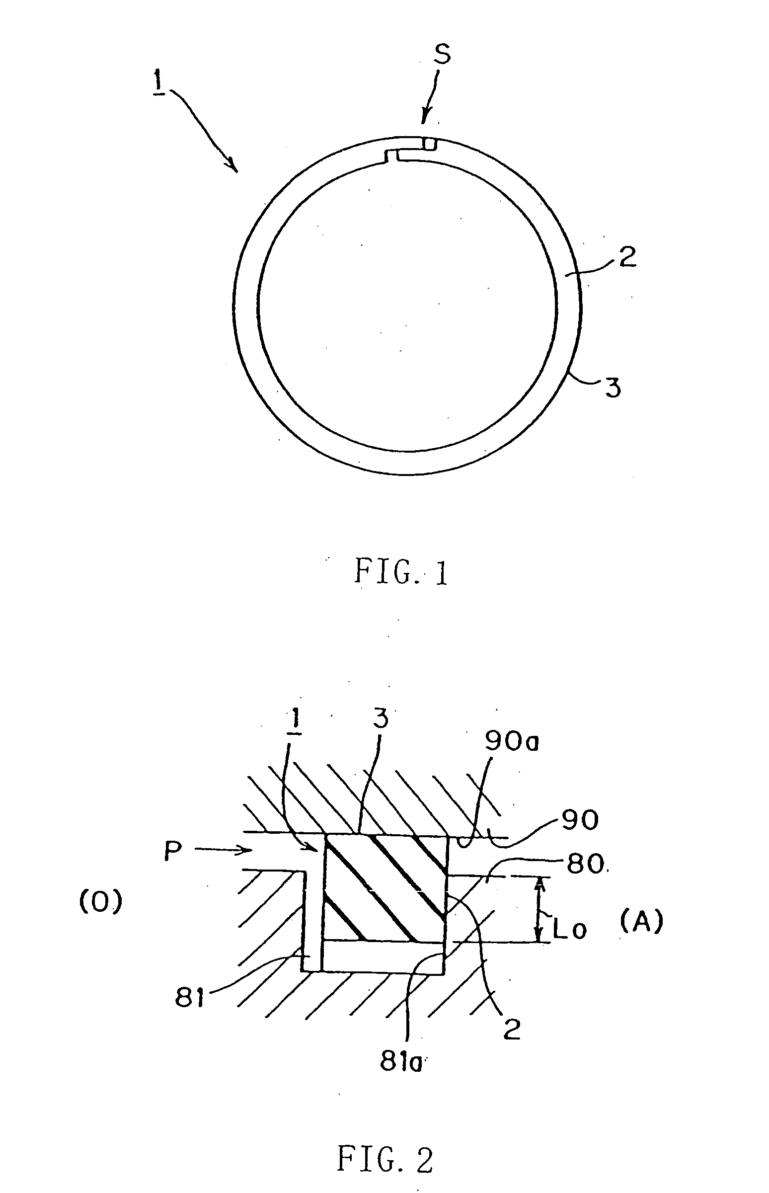
[0063]FIG. 1 is a schematic top plan view of the seal ring according to the first embodiment of the invention. FIG. 2 is a schematic section showing the state, in which the seal ring according to the first embodiment of the invention is mounted.

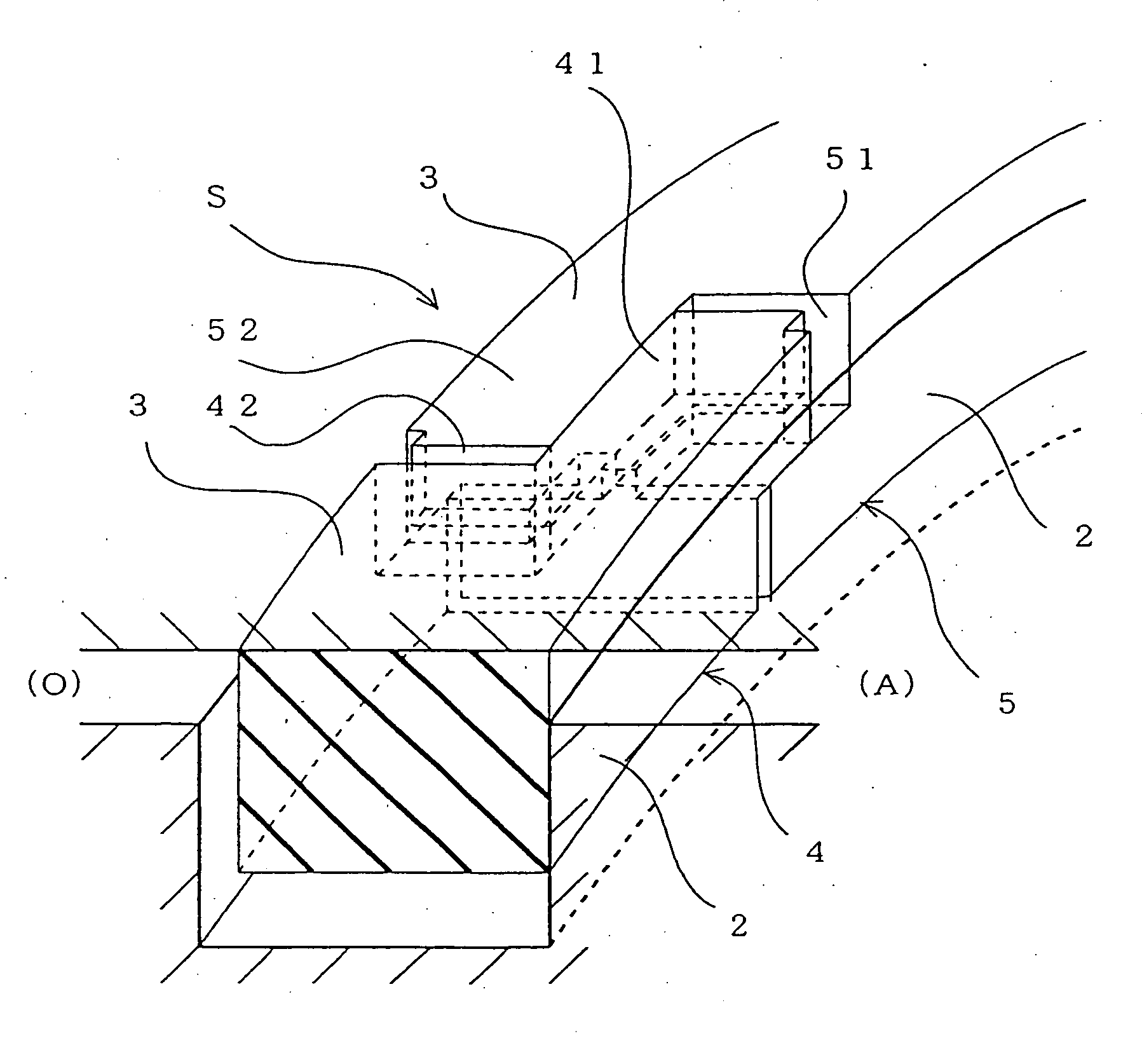
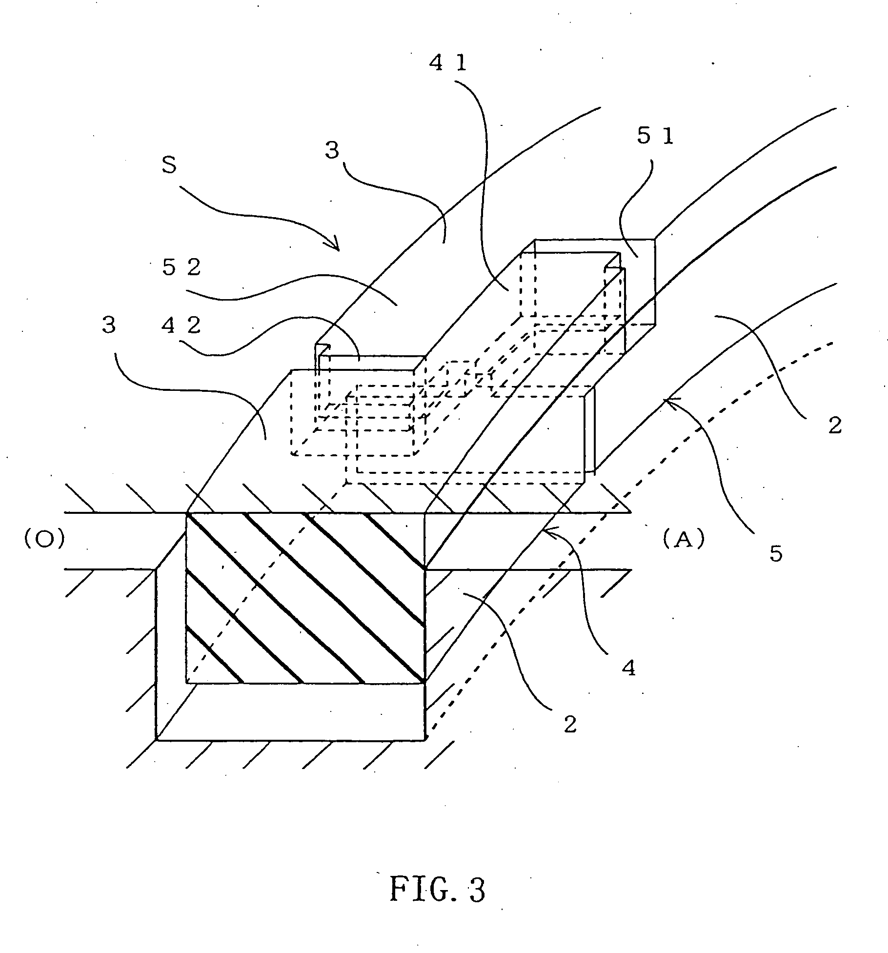
[0064] The seal ring 1 according to this embodiment seals an annular clearance between two members, which are assembled to turn freely and concentrically of each other, as shown in FIG. 2. Here, the annular clearance is formed between a housing 90 having a bore and a shaft 80 inserted in the bore. The seal ring 1 is mounted for use in an annular groove 81 formed in the shaft 80.

[0065] The seal ring 1 is provided with a first seal face 2 and a second seal fa...

second embodiment

[0121]FIG. 9 shows a second embodiment of the invention. In the aforementioned first embodiment, a portion of the passage is constructed by forming the groove only in the projection side disposed in the cut end portion. In this embodiment, a portion of the passage is constructed by forming a groove in the depression side, too.

[0122] The remaining constructions and actions are identical to those of the first embodiment so that their descriptions are omitted by designating the identical components by the common reference numerals.

[0123]FIG. 9 is a schematic section presenting a section in the cut portion of the seal ring according to the second embodiment of the invention. FIG. 9 schematically presents a section corresponding to the cut face of the upper portion of FIG. 6A.

[0124] In this embodiment, as shown, there is formed a groove M8 having a trapezoidal section generally perpendicular in the edge direction to the angle, at which the two adjoining outer wall faces (i.e., the sec...


PUM


Abstract

A seal ring for sealing an annular clearance between two members which are disposed for free rotations relative to each other. At a cut portion which is cut at a portion of the seal ring, there is formed a passage for allowing leakage when the cut end portions engage with each other. This passage is given a sectional shape of square or the like. This passage improves an abrasion resistance.

Description

TECHNICAL FIELD [0001] The present invention relates to a seal ring for sealing an annular clearance between two members which can rotate relative to each other. BACKGROUND ART [0002] In the related art, the seal ring of this kind is used in a hydraulic apparatus such as an automatic transmission of an automobile. [0003] A seal ring according to the related art will be described with reference to FIG. 10 to FIG. 13. FIG. 10 is a schematic top plan view of a seal ring according to the related art. FIG. 11 is a schematic section showing the state, in which the seal ring according to the related art is mounted. [0004] On the other hand, FIG. 12 presents schematic views of the seal ring according to the related art. [0005] Moreover: FIG. 12A is a schematic, partial top plan view; FIG. 12B is a section b-b of FIG. 12A; and FIG. 12C is a side elevation taken in the direction of c of FIG. 12A. FIG. 13 is a perspective view of a cut portion of the seal ring according to the related art. Thi...

Claims


Application Information

Patent Timeline
Patent Type & Authority Applications(United States)
IPC IPC(8): F16J9/14F16J15/324F16J15/3272
CPCF16J15/3272F16J9/14F16J15/54
Inventor WATANABE, HIDEYANAKAOKA, SHINYATANABE, YASUAKIEGUCHI, NOBUYUKI
Owner NOK CORP
Why Eureka
Try Eureka