Actuator

Inactive Publication Date: 2005-06-02
SEIKO EPSON CORP
View PDF8 Cites 15 Cited by
  • Summary
  • Abstract
  • Description
  • Claims
  • Application Information

AI Technical Summary

Benefits of technology

[0008] It is therefore an object of the present invention to provide an actuator capable of operating at

Problems solved by technology

However, there is a problem in that it is difficult to rotate the polygon mirror at much higher speed than the speed available at the present.
Further, although a larger motor is required in order to rotate the polygon mirror at higher speed, use of such a larger motor arises a problem in that it is difficult to miniaturize the size of an apparatus in which the polygon mir

Method used


Image

  • Actuator
  • Actuator
  • Actuator

Examples


Example

FIRST EMBODIMENT

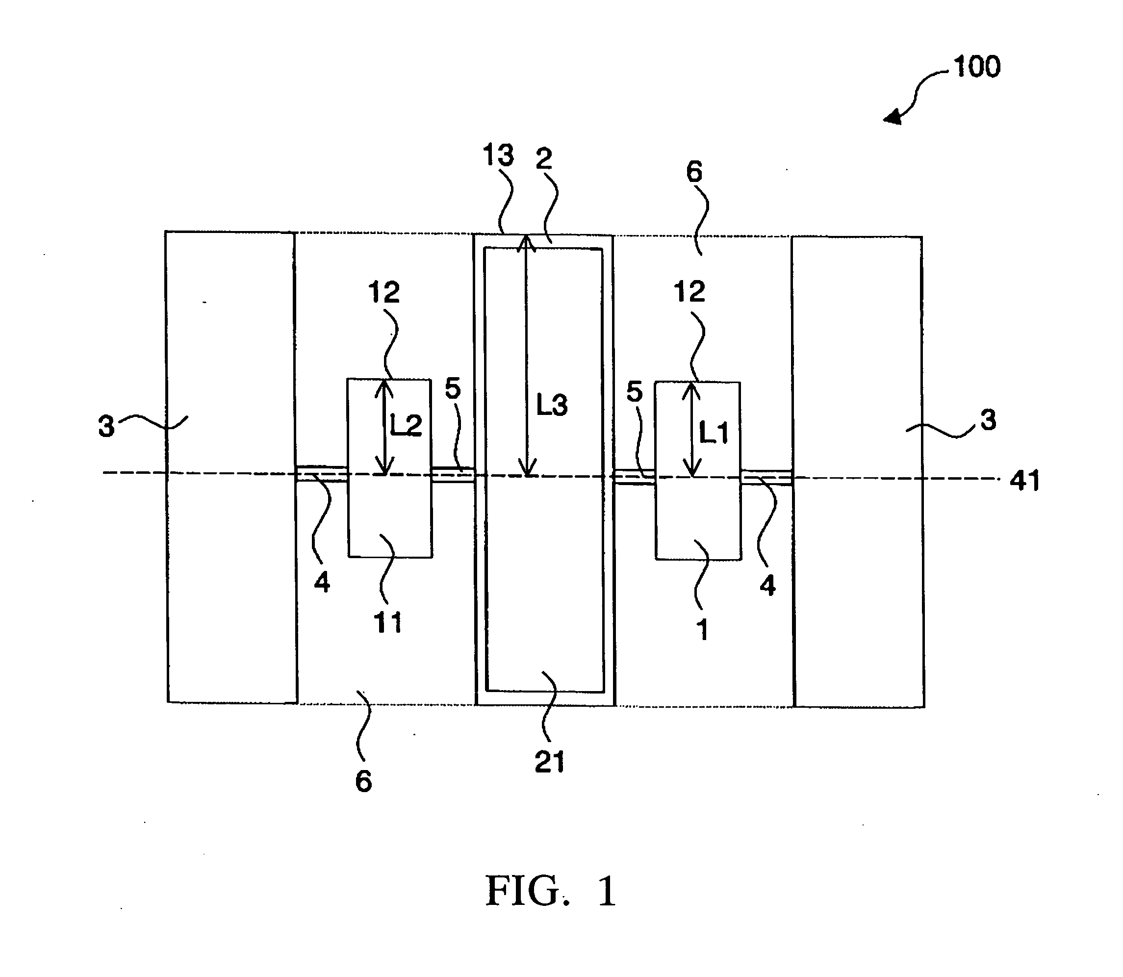
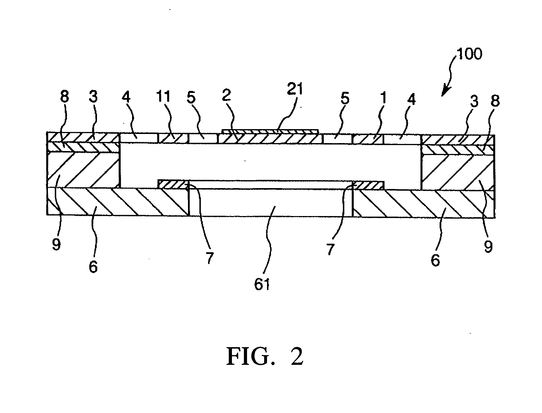
[0051] First, a first embodiment of the actuator according to the present invention will be described. FIG. 1 is a plan view which shows the first embodiment of the actuator according to the present invention. FIG. 2 is a cross-sectional view which shows the first embodiment of the actuator according to the present invention. FIG. 3 is a plan view which shows a counter substrate and electrodes of the first embodiment. FIG. 4 is a drawing which shows an example of the alternating voltage to be applied to the actuator shown in FIG. 1. FIG. 5 is a graph which shows the frequency of an alternating voltage applied and the resonance curves of a first mass portion and a second mass portion. In the following description, it is to be noted that the upper side, the lower side, the right side and the left side in FIGS. 1 and 3 will be referred to as the “upper side”, “lower side”, “right side” and the “left side”, respectively.

[0052] An actuator 100 shown in FIG. 1 includes a...

Example

SECOND EMBODIMENT

[0081] Next, a second embodiment of the actuator according to the present invention will be described. FIG. 7 is a plan view which shows the second embodiment of the actuator according to the present invention. Hereinafter, an actuator 100A shown in FIG. 7 will be described by focusing on the difference between the first and second embodiments, and therefore a description of the same points will be omitted.

[0082] As shown in FIG. 7, the actuator 100A of this embodiment includes two pairs of first elastic connecting portions 4′ and two pairs of second elastic connecting portions 5′. The two pairs of first elastic connecting portions 4′ connect the first mass portions 1, 11 to the supporting portions 3, 3, respectively, so that each of the first mass portions 1, 11 can rotate with respect to the corresponding supporting portion 3. The two pairs of second elastic connecting portions 5′ connect the second mass portion 2 to the first mass portions 1, 11, respectively, ...

Example

THIRD EMBODIMENT

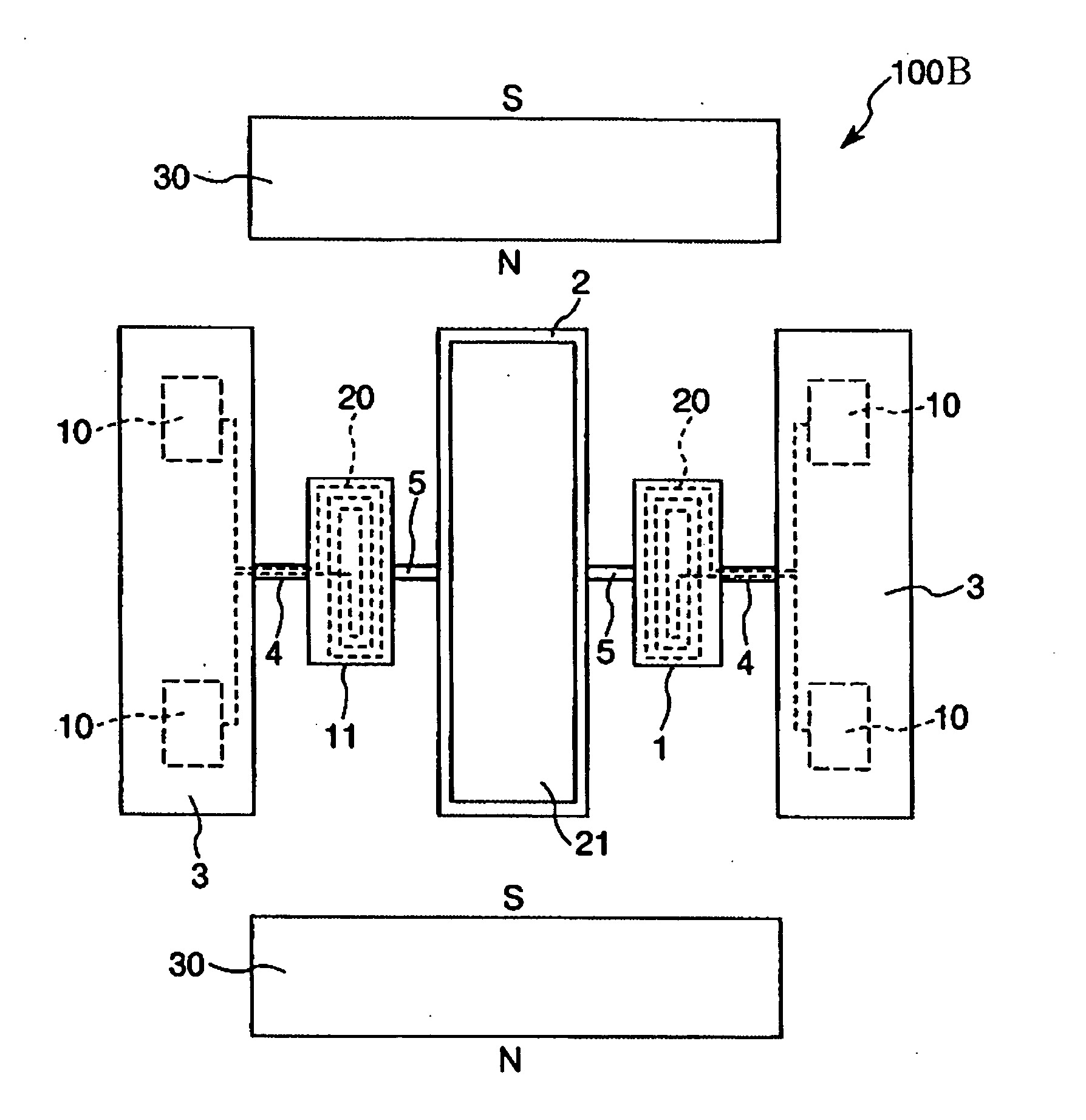
[0084] Next, a third embodiment of the actuator according to the present invention will be described. FIG. 8 is a plan view which shows the third embodiment of the actuator according to the present invention. Hereinafter, an actuator 100B shown in FIG. 8 will be described by focusing on the difference between the first and third embodiments, and therefore a description of the same points will be omitted. The actuator 100B of this embodiment is driven by electromagnetic force (that is, by Lorentz force).

[0085] Specifically, as shown in FIG. 8, the actuator 100B includes four terminals 10 provided in the supporting portions 3, 3 through insulating films (not shown in FIG. 8), two coils 20 respectively provided on the surfaces of the first mass portions 1, 11 (that is, the surfaces of the first mass portions 1, 11 which do not face the counter substrate 6), a pair of permanent magnets 30, 30 provided on both sides of the first mass portions 1, 11 so that the first mas...


PUM


Abstract

An actuator 100 of the type employing a two-degree-of-freedom vibration system includes: a pair of first mass portions 1, 11; a second mass portion 2 provided between the pair of first mass portions 1, 11; a pair of supporting portions 3, 3 for supporting the pair of first mass portions 1, 11 and the second mass portion 2; at least a pair of first elastic connecting portions 4, 4 which respectively connect the first mass portions 1, 11 to the supporting portions 3, 3 so that each of the first mass portions 1, 11 can rotate with respect to the supporting portions 3, 3; and at least a pair of second elastic connecting portions 5, 5 which respectively connect the second mass portion 2 to the first mass portions 1, 11 so that the second mass portion 2 can rotate with respect to the first mass portions 1, 11. Each of the first mass portions 1, 11 is driven by the application of an alternating voltage, causing the second mass portion 2 to rotate.

Description

BACKGROUND OF THE INVENTION [0001] 1. Field of the Invention [0002] The present invention relates to an actuator, and in particular relates to an actuator of the type employing a two-degree-of-freedom vibration system. [0003] 2. Description of the Prior Art [0004] There is known a polygon mirror (rotary polyhedron) as an actuator provided in laser printers, for example. In such a printer, in order to achieve higher-resolution and higher-quality printed output as well as higher-speed printing, it is necessary to rotate the polygon mirror at higher speed. Currently, an air bearing is used to rotate the polygon mirror at high speed with stability. However, there is a problem in that it is difficult to rotate the polygon mirror at much higher speed than the speed available at the present. Further, although a larger motor is required in order to rotate the polygon mirror at higher speed, use of such a larger motor arises a problem in that it is difficult to miniaturize the size of an app...

Claims


Application Information

Patent Timeline
IPC IPC(8): G02B26/00G03G15/00H02K33/00H02K33/16H02N1/00
CPCH02N1/006H02K33/16
Inventor YODA, MITSUHIRO
Owner SEIKO EPSON CORP
Why Eureka
Try Eureka