
Hard drive test fixture

a test fixture and hard drive technology, applied in the field of hard drive test fixtures, can solve the problems of relative cost of fabrication

Inactive Publication Date: 2005-06-02
PEMSTAR
View PDF33 Cites 53 Cited by
  • Summary
  • Abstract
  • Description
  • Claims
  • Application Information

AI Technical Summary

Benefits of technology

[0007] In one embodiment, rails are attached to the base of the pan for providing structural support to the pan and to provide a bearing surface for positioning of the hard drive. A connection card is located in place between the rails and is adapted for connection to the hard drive. The test fixture also includes an ejection rod for facilitating removal of the hard drive from the test fixture.
[0008] In an alternate embodiment, the test fixture includes a pan, a test card coupled to the pan, a first bearing surface coupled to the pan, and a second bearing surfaced coupled to the pan. The first and second bearing are each adapted to guide a hard drive of a particular size to the test card. In this configuration, the test fixture is easily adapted to test hard drives of varying sizes.

Problems solved by technology

Typical hard drive test fixtures in the prior art are precision machined to close tolerance, making them relatively expensive to fabricate.
Furthermore, prior art test fixtures are typically built to handle only one type of hard drive.

Method used


Image

  • Hard drive test fixture
  • Hard drive test fixture
  • Hard drive test fixture

Examples


Embodiment Construction

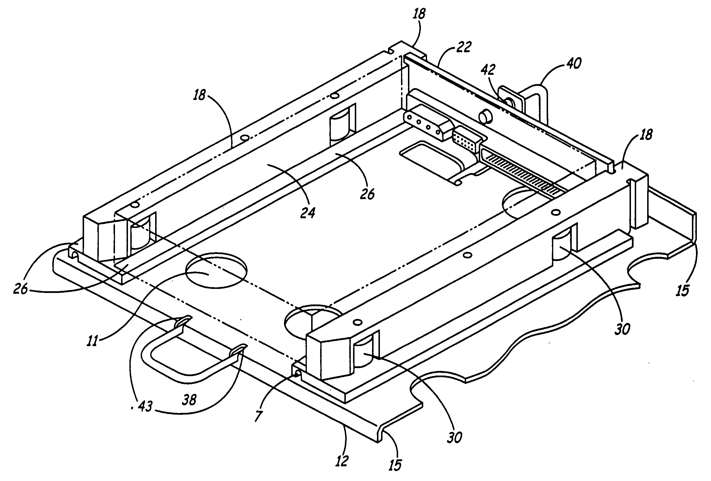
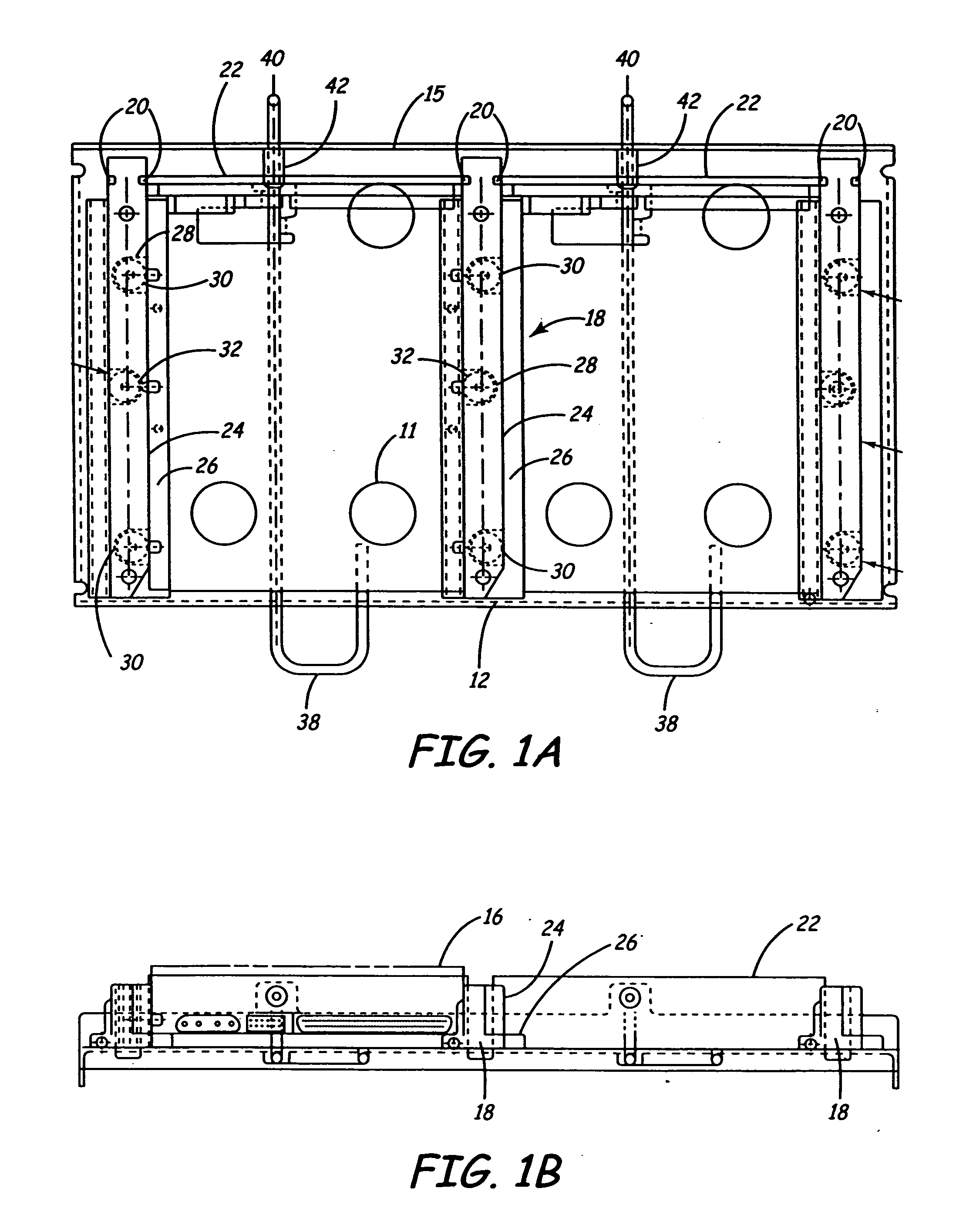
[0022] As shown in FIG. 1A, the present invention is a test fixture 10 specially adapted to support a hard drive during testing and to interface thereto. The subject invention is especially suited for use within an environmental chamber, but is easily adapted to cooperate with racks or storage cabinets that are generally known in the art.

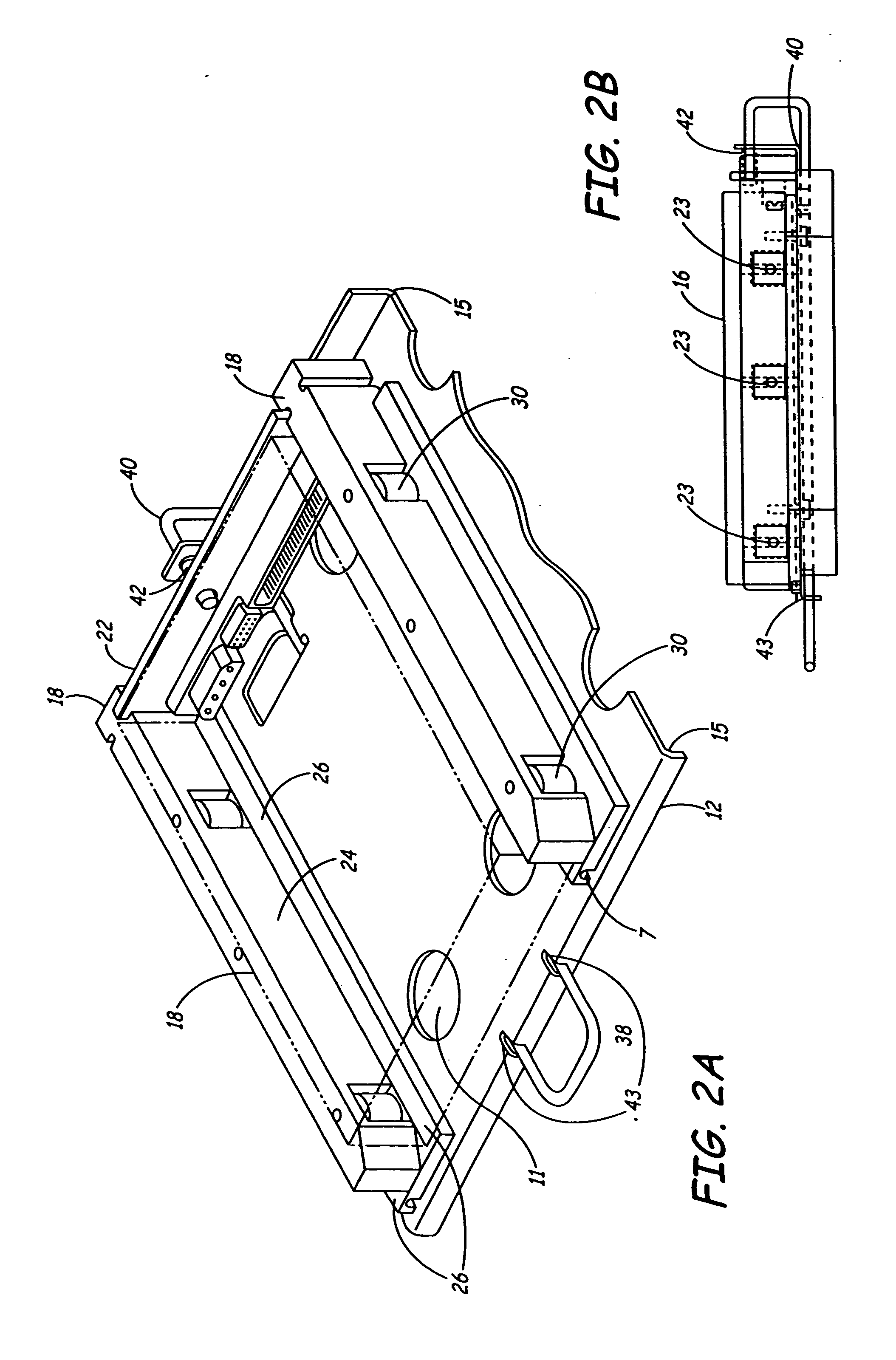
[0023] As shown in FIGS. 1A and 1B, in one embodiment, a pan 12 forms the “backbone” of the fixture 10. Preferably, the pan 12 is fabricated from nonmagnetic stainless steel. Two bends 15 extend longitudinally along the pan stiffening the pan 12. Airflow holes 11 are punched in the pan 12 in a pattern generated to maximize the flow of air through and around the inserted hard disk drive 16 (shown by dashed lines in FIGS. 2A and 2B), while maintaining adequate stiffness to provide rigidity.

[0024] Connected to the pan 12 is a bearing surface which serves to guide a hard drive 16 during insertion into the fixture 10, and to locate the hard drive 16 du...


PUM


Abstract

The present invention is a hard drive test fixture for supporting a hard drive during quality control testing. The test fixture includes a pan having a base. Rails are attached to the base of the pan for providing structural support to the pan and for positioning of the hard drive. A connection card is removably attached to the rails and is adapted for connection to the hard drive. The test fixture includes an ejection rod for facilitating removal of the hard drive from the test fixture.

Description

CROSS-REFERENCE TO RELATED APPLICATION(S) [0001] This application claims priority from provisional No. 60 / 286,732, dated Apr. 25, 2001.FIELD OF THE INVENTION [0002] The present invention relates generally to an environmental chamber for testing hard drives. More specifically, the present invention relates to a fixture for securing and testing a hard drive while in an environmental chamber. BACKGROUND OF THE INVENTION [0003] Computer hard drives are generally subjected to a “burn-in” testing procedure conducted in an environmentally controlled test chamber. These chambers are designed to isolate the drive from vibrations, from temperature changes, and from humidity changes so that the drive manufacturer can obtain accurate performance test results. [0004] Computer hard drives are also usually subjected to thermal testing or environmental conditioning testing during the design and prototyping phases of the manufacturing process. This testing, also known as “final verification” testing...

Claims


Application Information

Patent Timeline
IPC IPC(8): G11B33/02G11B33/12H05K7/14
CPCG11B33/022G11B33/121H05K7/1411G11B33/128G11B33/125
Inventor WANEK, DONALD J.SANDS, RICHARD
Owner PEMSTAR
Learn More