Quartz-enhanced photoacoustic spectroscopy

a photoacoustic spectroscopy and quartz technology, applied in the field of photoacoustic spectroscopy, can solve the problems of achieving longer t's in a fluid-filled sample cell, expanding or contracting materials within the environment,

Inactive Publication Date: 2005-06-02
RICE UNIV
View PDF14 Cites 101 Cited by
  • Summary
  • Abstract
  • Description
  • Claims
  • Application Information

AI Technical Summary

Problems solved by technology

Such forms of energy cause expansion or contraction of materials within the environment.
Achieving longer t's in a fluid-filled sample cell 18 is problematic because of sample cell dimension constraints in addition to intrinsic losses related to gas viscosity and other relaxation processes.

Method used


Image

  • Quartz-enhanced photoacoustic spectroscopy
  • Quartz-enhanced photoacoustic spectroscopy
  • Quartz-enhanced photoacoustic spectroscopy

Examples


example

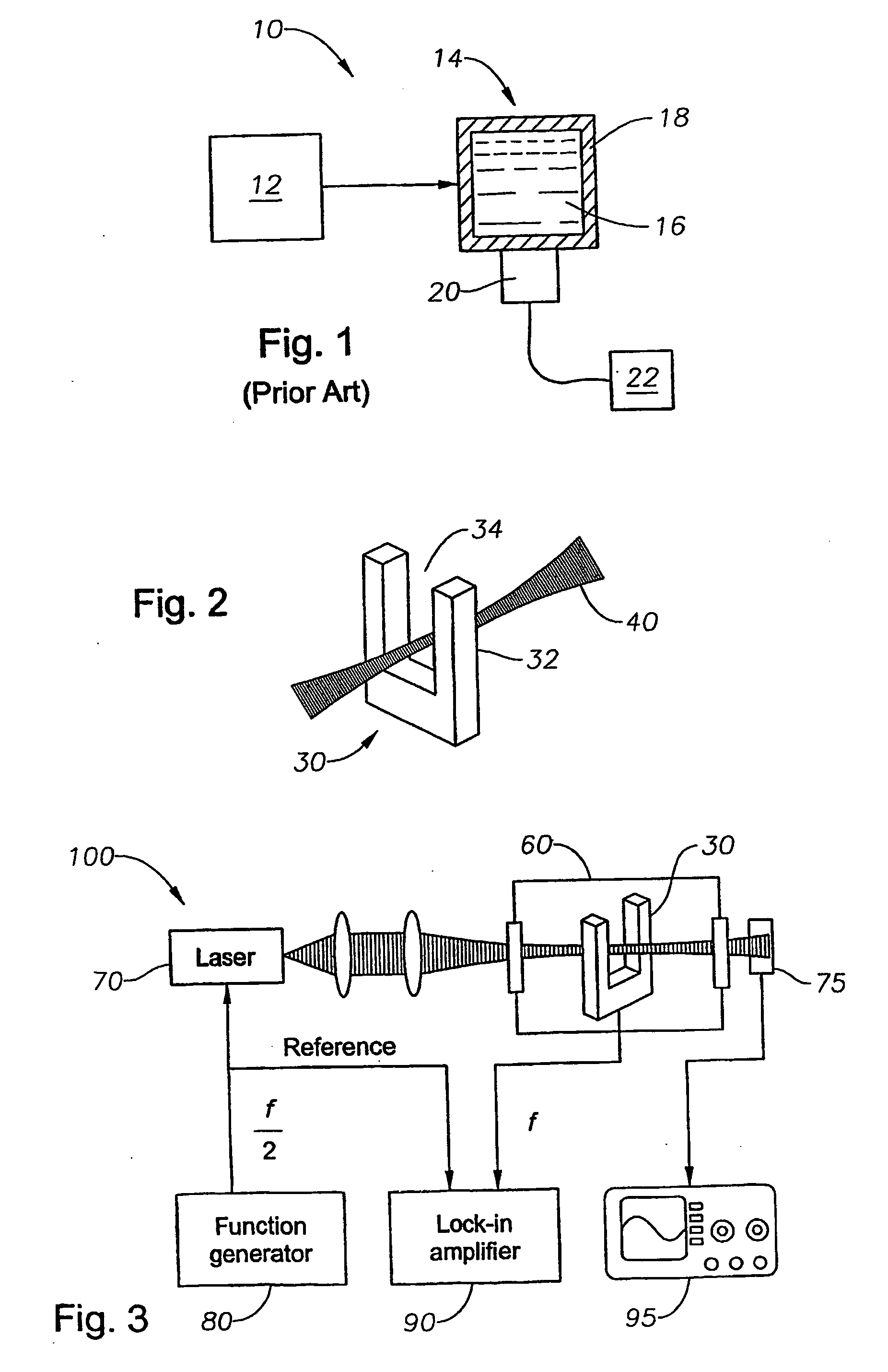
[0038] A commercially available tuning fork, such as might be used in a wristwatch, (tuning fork R38-32.768-KHZ-Raltron) is obtained. The overall tuning fork dimensions are 6 mm×1.4 mn×0.2 mm, with each prong being 3.8 mm long and 0.6 mm wide. The gap between the prongs is 0.2 mm.

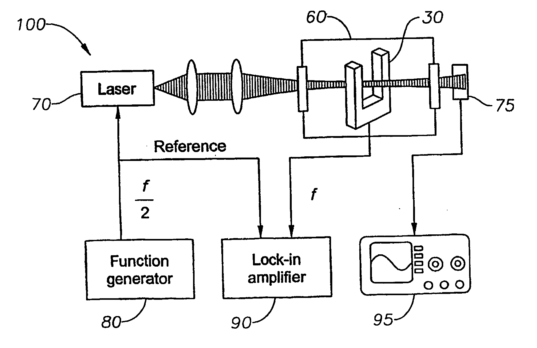
[0039] As discussed above, several configurations for detecting the photoacoustic signal with a tuning fork 30 are shown in FIGS. 2 and 6-10 and observations using the present tuning fork will be described.

[0040]FIGS. 2 and 6 correspond to aiming laser light 40 at the tuning fork 30 from different directions. In FIG. 2, the laser beam 40 is perpendicular to the tuning fork plane, while in FIG. 6 the laser beam 40 is in the tuning fork plane. Configuration 6 results in a longer effective pathlength but is more sensitive to alignment because the laser beam is directly contacting the fork.

[0041]FIG. 7 presents a combination of a tuning fork 30 with an acoustic resonator or tube 50. Resonator 50 preferably c...


PUM

PropertyMeasurementUnit
sizeaaaaaaaaaa
resonant frequencyaaaaaaaaaa
frequenciesaaaaaaaaaa

Abstract

Methods and apparatus for detecting photoacoustic signals in fluid media are described. The present invention differs from conventional photoacoustic spectroscopy in that rather than accumulating the absorbed energy in the fluid of a sample cell, the absorbed energy is accumulated in an acoustic detector or sensitive element. In a preferred embodiment, the acoustic detector comprises piezoelectric crystal quartz. The quartz is preferably in the shape of a tuning fork.

Description

STATEMENT REGARDING FEDERALLY SPONSORED RESEARCH OR DEVELOPMENT [0001] None. FIELD OF THE INVENTION [0002] The present invention generally relates to the field of photoacoustic spectroscopy. More specifically, the present invention relates to detecting photoacoustic signals in a fluid and accumulating the signals in an acoustic detector. BACKGROUND OF THE INVENTION [0003] Photoacoustic spectroscopy (PAS) is an analytical method that involves stimulating a sample by light and subsequently detecting sound waves emanating from the sample. Typically, only a narrow range of wavelengths of light are introduced into a sample. Such narrow range of wavelengths of light can be formed by, for example, a laser. Utilization of only a narrow range of wavelengths can enable pre-selected molecular transitions to be selectively stimulated and studied. [0004] A photoacoustic signal can occur as follows. First, light stimulates a molecule within a sample. Such stimulation can include, for example, abs...

Claims


Application Information

Patent Timeline
Patent Type & Authority Applications(United States)
IPC IPC(8): G01N21/17
CPCG01N21/1702G01N29/2425G01N2291/0427G01N2021/1708G01N2021/1704
Inventor KOSTEREV, ANATOLIY A.
Owner RICE UNIV
Why Eureka
Try Eureka