Two-dimensional scanning apparatus and scanning type image displaying apparatus using the same

a two-dimensional scanning and display apparatus technology, applied in the direction of color television details, television systems, instruments, etc., can solve the problems of trapezoid distortion, difficult electrical correction, image distortion of two-dimensional scanning images on the surface, etc., and achieve the effect of high quality

Inactive Publication Date: 2005-06-02
CANON KK
View PDF14 Cites 22 Cited by
  • Summary
  • Abstract
  • Description
  • Claims
  • Application Information

AI Technical Summary

Benefits of technology

[0011] It is an object of the present invention to provide a two-dimensional scanning apparatus which can well correct the image distortion of a scanning image displayed by two-dimensionally optically scanning with a beam deflected by deflecting means. Particularly it is an object of the present invention to provide a two-dimensional scanning apparatus carrying thereon a two-dimensional scanning optical system which can well correct TV distortion caused by a beam being two-dimensionally deflected by deflecting means and trapezoid distortion caused by an image being obliquely projected onto a surface to be scanned, and capable of always displaying an image of high quality free of image distortion, and a scanning type image displaying apparatus using the same.

Problems solved by technology

It is generally known that at this time, image distortion occurs to the two-dimensional scanning image on the surface to be scanned.
Also, when an image is obliquely projected onto the surface to be scanned, trapezoid distortion occurs.
H08-146320, TV distortion is corrected by the f·sin θ characteristic of the scanning optical system and electrical correction, however there has been the problem that it is difficult to electrically correct it.
H11-84291, it is also made possible to have a wide scanning angle, correct distortion of a constant speed scanning property and achieve telecentricity, however TV distortion caused by two-dimensional scanning cannot be corrected.
In the publication, there has been the problem that when image distortion such as TV distortion and trapezoid distortion occurs, the quality of the image is deteriorated, so that an image of high quality cannot be displayed.

Method used


Image

  • Two-dimensional scanning apparatus and scanning type image displaying apparatus using the same
  • Two-dimensional scanning apparatus and scanning type image displaying apparatus using the same
  • Two-dimensional scanning apparatus and scanning type image displaying apparatus using the same

Examples


first embodiment

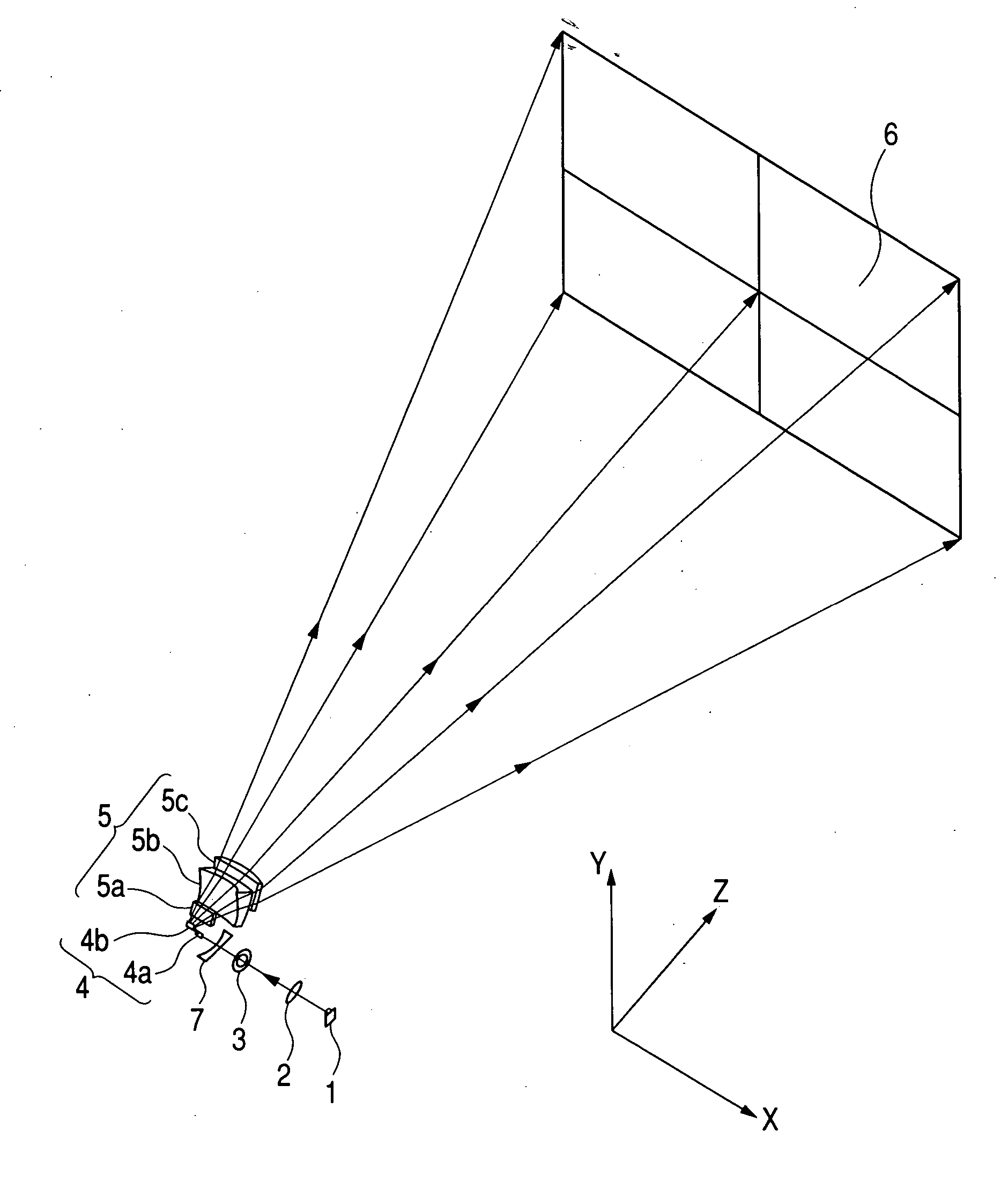
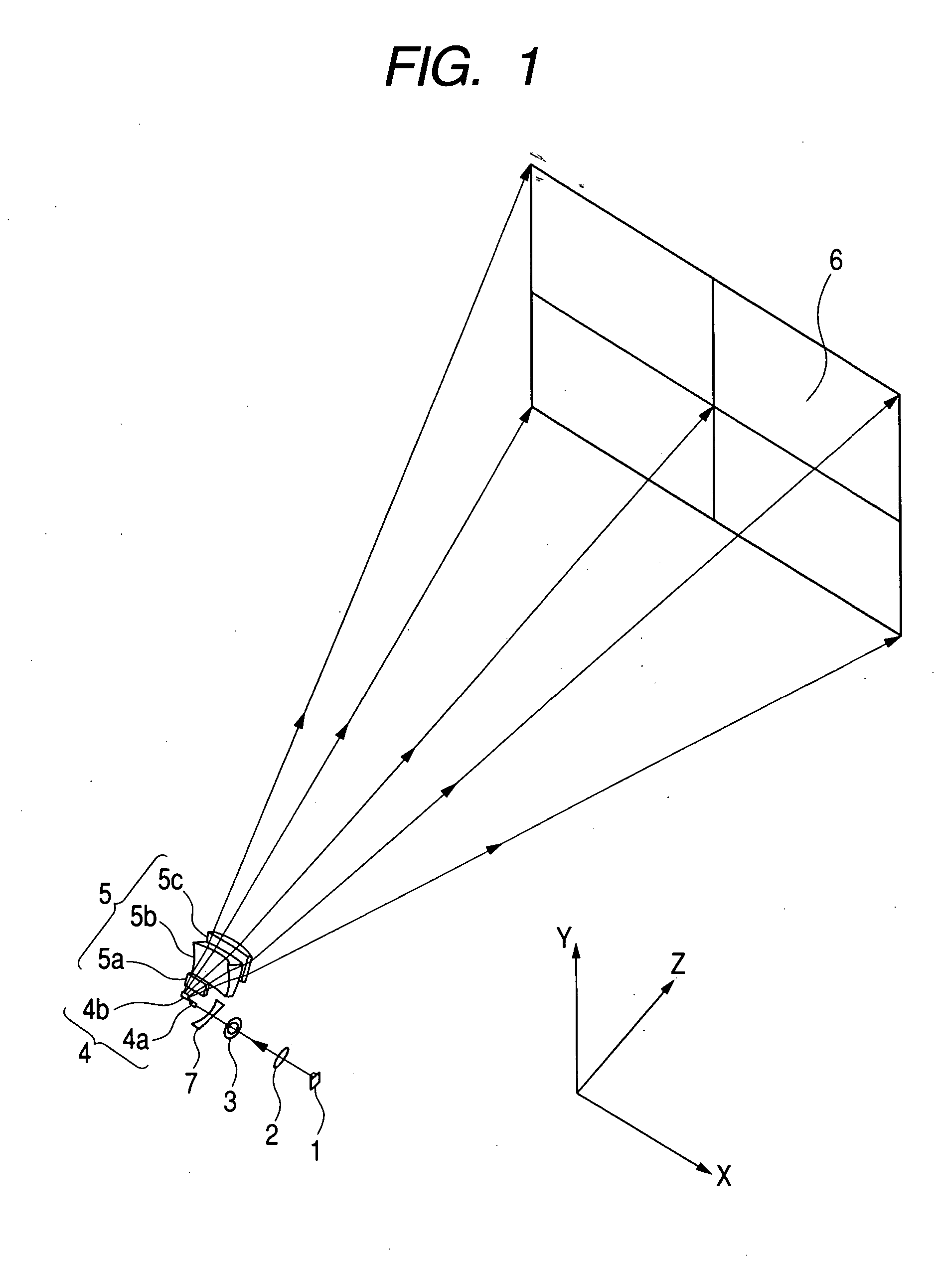
[0062]FIG. 1 is a perspective view of the essential portions of a scanning type image displaying apparatus using a two-dimensional scanning apparatus according to a first embodiment of the present invention, and FIG. 2 is a schematic view of the essential portions of the first embodiment of the present invention.

[0063] In these figures, the reference numeral 1 designates light source means comprising, for example, a red semiconductor laser or the like.

[0064] The reference numeral 2 denotes a condensing lens (collimator lens) which converts a divergent beam emitted from the light source means 1 into a parallel beam (or a convergent beam or a divergent beam).

[0065] The reference numeral 3 designates an aperture stop which limits the passing beam to thereby shape the shape of the beam.

[0066] The reference numeral 7 denotes an anamorphic incidence optical system weaker in refractive power in a first one-dimensional direction (first direction) than that in a second one-dimensional di...

second embodiment

[0122]FIG. 13 is a cross-sectional view (vertical cross-sectional view) of the essential portions of a two-dimensional scanning apparatus according to a second embodiment of the present invention in a vertical direction. In FIG. 13, the same elements as the elements shown in FIG. 1 are given the same reference characters.

[0123] The difference of this embodiment from the aforedescribed first embodiment is that the lens shapes of the scanning lenses 5a, 5b and 5c constituting the two-dimensional scanning optical system 5 are changed. In the other points, the configuration and optical action of the present embodiment are substantially similar to those of the first embodiment, whereby a similar effect can be obtained.

[0124] That is, in FIG. 13, the reference numeral 5 designates the two-dimensional scanning optical system (scanning optical means) having three first, second and third scanning lenses 5a, 5b and 5c having lens shapes different from those in the first embodiment, and it c...

third embodiment

[0141]FIG. 16 is a cross-sectional view (vertical cross-sectional view) of the essential portions of a two-dimensional scanning apparatus according to a third embodiment of the present invention in a vertical direction. In FIG. 16, the same elements as the elements shown in FIG. 1 are given the same reference characters.

[0142] The difference of this embodiment from the aforedescribed second embodiment is that besides the aspherical Y toric surfaces, configuring a two-dimensional scanning optical system 5 having a free curved surface having no correlation between the radii of curvature in the meridian line direction and the sagittal line direction. In the other points, the construction and optical action of the present embodiment are substantially same as those of the first embodiment, whereby a similar effect can be obtained.

[0143] That is, in FIG. 16, the reference numeral 5 designates a two-dimensional scanning optical system (scanning optical means) having three first, second a...


PUM


Abstract

A two-dimensional scanning apparatus has light source means, deflecting means for deflecting a beam emitted from the light source means in a two-dimensional direction, and scanning optical means for directing the beam deflected by the deflecting means onto a surface to be scanned. The scanning optical means has one or more scanning optical element, and one or more surfaces of one or more of the aforementioned one or more scanning optical elements are anamorphic surfaces, and the anamorphic surfaces on the aforementioned one or more surfaces are anamorphic surfaces monotonously changing in a radius of curvature of which the absolute value of the radius of curvature in a first one-dimensional direction continuously decreases from one side toward the other side along a second one-dimensional direction orthogonal to the first one-dimensional direction. Thus, there can be supplied a two-dimensional scanning apparatus which can well correct TV distortion caused by the two-dimensional deflection of the beam by the deflecting means and trapezoid distortion caused by an image being obliquely projected onto a surface to be scanned, and a scanning type image displaying apparatus using the same.

Description

BACKGROUND OF THE INVENTION [0001] 1. Field of the Invention [0002] This invention relates to a two-dimensional scanning apparatus and a scanning type image displaying apparatus using the same, and particularly is adapted to two-dimensionally scan a beam (deflected beam) deflected by deflecting means to thereby project and display a two-dimensional image on a surface to be scanned (a screen surface). [0003] 2. Related Background Art [0004] There have heretofore been various two-dimensional scanning apparatuses adapted to two-dimensionally deflect a beam emitted from light source means by deflecting means, and two-dimensionally optically scan a surface to be scanned with a spot to thereby form a two-dimensional image (see, for example, Japanese Patent Application Laid-Open No. H08-146320). [0005] In Japanese Patent Application Laid-Open No. H08-146320, a beam emitted from light source means is deflected by deflecting means capable of two-dimensional deflection, and a surface to be sc...

Claims


Application Information

Patent Timeline
Patent Type & Authority Applications(United States)
IPC IPC(8): G02B13/08G02B13/18G02B26/10H04N5/74
CPCG02B26/101
Inventor ISHIHARA, KEIICHIRO
Owner CANON KK
Why Eureka
Try Eureka