Light emitting device and display unit using the light emitting device and reading device

a technology of light emitting devices and reading devices, which is applied in the direction of lighting and heating apparatus, process and machine control, instruments, etc., can solve the problems of inability to apply a method, increase the cost of driving circuits, and large variation in white point and luminance characteristics, etc., to achieve control of white point and/or luminance properties

Inactive Publication Date: 2005-06-02
SHARP KK
View PDF5 Cites 156 Cited by
  • Summary
  • Abstract
  • Description
  • Claims
  • Application Information

AI Technical Summary

Benefits of technology

[0014] The present invention has been proposed in view of various problems as described above. The objective of the present invention is to provide a light-emitting device which can monitor emission intensit...

Problems solved by technology

However, a light source using a white cold cathode fluorescent tube and a white LED have a problem that white point and luminance characteristics vary largely depending on changes in temperature characteristics and changes over time.
If the frequency is set too high, the cost for the driving circuit increases.
First, the time-division switching method described in Japanese Laid-Open Publication No. 10-49074 has an advantage that the emission intensities of the light sources can be monitored by a single type optical sensor, but the method has a critical problem that it is effective for only the time-division method, in which light sources are turned on one type at a time in turn, and it cannot be applied to a method other than the time-division method.
Further, the simultaneous light-emitting method described in Japanese Laid-Open Publication No. 11-295689 has a problem that the cost is high because a color separation filter is necessar...

Method used


Image

  • Light emitting device and display unit using the light emitting device and reading device
  • Light emitting device and display unit using the light emitting device and reading device
  • Light emitting device and display unit using the light emitting device and reading device

Examples


first embodiment

SECOND DRIVING EXAMPLE OF FIRST EMBODIMENT

[0062] In FIG. 3 showing the first driving example of the first embodiment, three types of LEDs are turned on one by one in turn by the light-emission control means 11A during a monitoring period, and, while one type of LED is turned on, the other two types of LEDs are turned off. Thus, there is extinction caused by turning off the two types of LEDs during a monitoring period, i.e. a decrease in an amount of light emitted from the light source unit 1, although it is a short period of time. One of the monitoring methods which avoids an influence of such extinction is the second driving example of the first embodiment. In this driving example, light-emission control means 11B, which is another example of the light-emission control means 11, turns on two of the three types of LEDs in turn at a time during the monitoring period and, while the two types of LEDs are turned on, the remaining one type of LED is turned off.

[0063]FIG. 4(a)-(c) shows ...

third embodiment

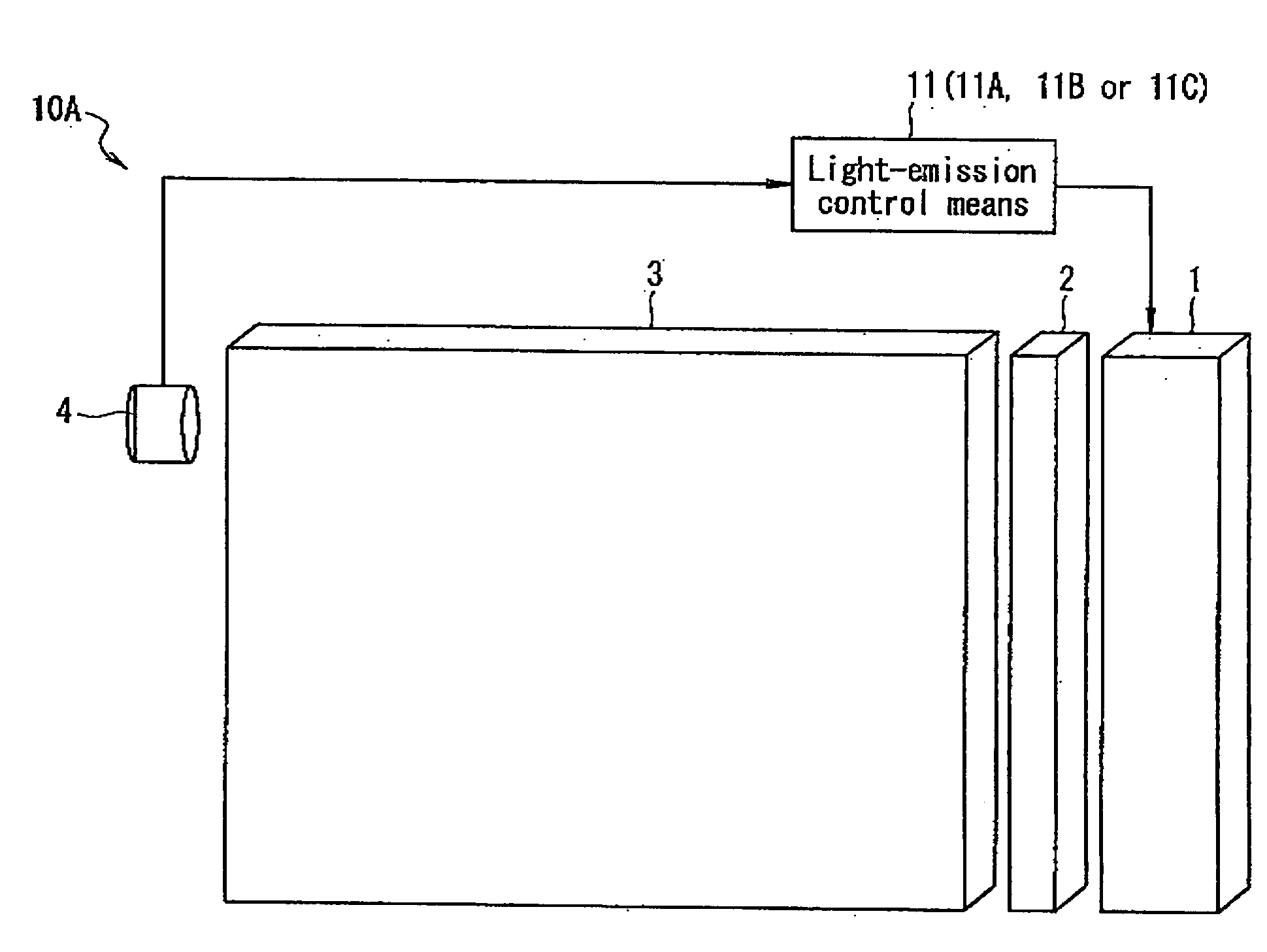
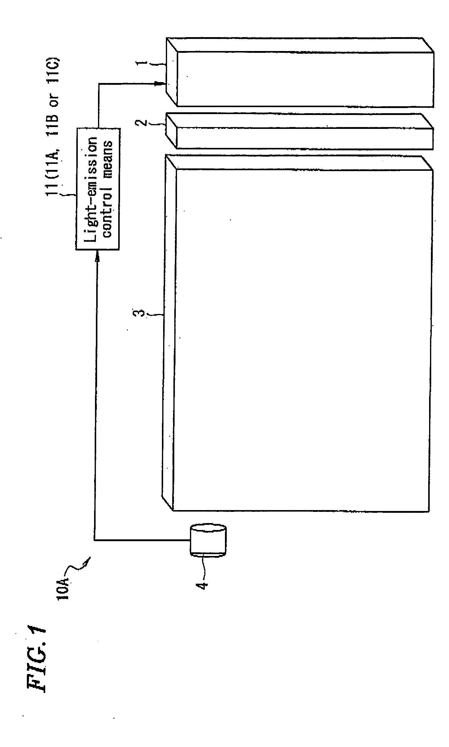
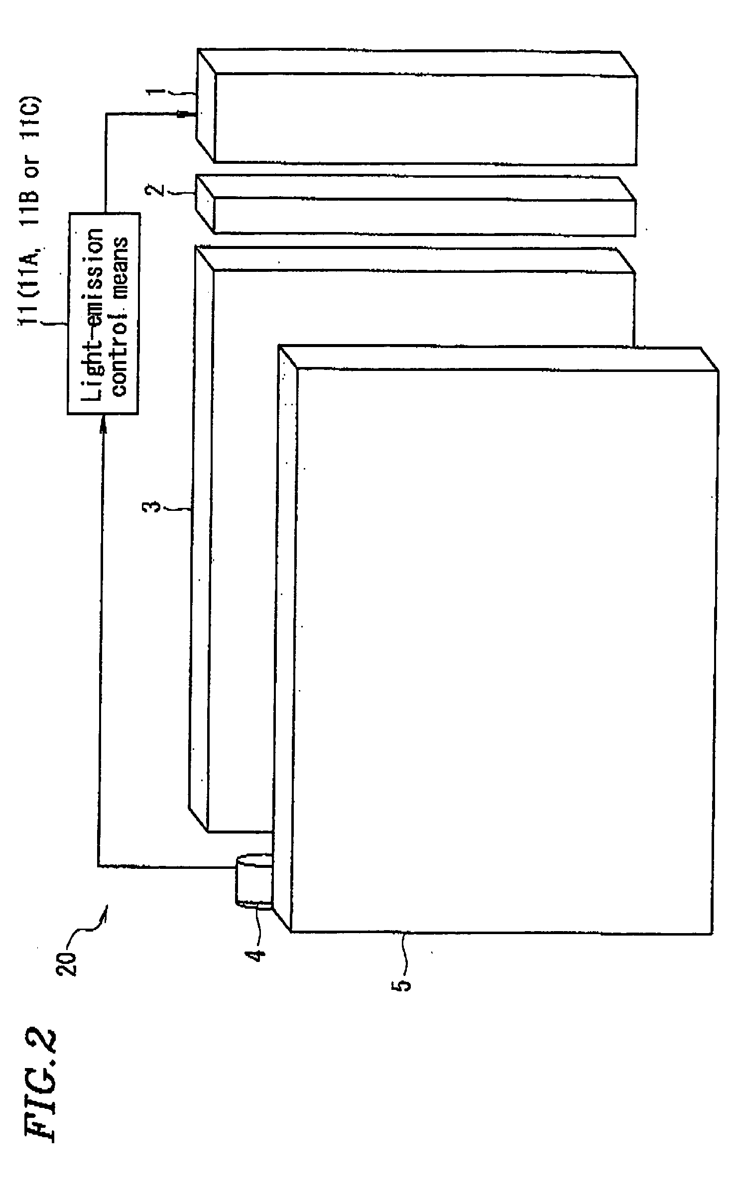
[0106]FIG. 10 schematically shows a light emitting device 10C of the third embodiment according to the present invention. In the third embodiment, the light emitting device 10C includes: a light source unit 1C provided with a plurality of light-emitting sources, comprising two types of light sources 2a and 2c; a light guide plate 3 for uniformly irradiating a plane with light from the light source unit 1C; a second light source unit 6 including a light source 2b of a type different from the above light sources; a light guide plate 7 for uniformly irradiating a plane with light from the second light source unit 6; an optical sensor 4 as a light detection means; and light emission control means 11 or 12 which receives emission intensity information of the light sources obtained by performing light emission control of the three types of the light sources for monitoring during a monitoring period as monitoring results from the optical sensor 4, and performs light emission control of the...

fourth embodiment

[0116] The light emitting device 10A. 10B, and 10C which has been described above can be applied to a read apparatus. In the fourth embodiment, the above-described light emitting device 10A, 10B, or 10C is applied to a read apparatus.

[0117]FIG. 11 shows an example; (a) schematically shows a read apparatus, and (b) schematically shows the light emitting device according to the present invention.

[0118] As shown in FIG. 11(a), the read apparatus 11 includes: a read portion 8 which operates as a scanner, copying machine or the like; a read copy holder 9 as a stage for putting a copy to be read, and a light-emitting device 10 for illuminating the copy.

[0119] As shown in FIG. 11(b), the light-emitting device 10 is formed of a light emitting portion 10a for emitting light so as to uniformly illuminate the copy, and a light source unit 10b in which multiple types of light sources are located. The light source unit 10b incorporates red, green and blue light sources and an optical sensor (...


PUM


Abstract

A light emitting device provided with a plurality of types of light sources having different light emitting colors and with a light emission control means for allowing light to emit, during a specified period of monitoring a light emitting intensity, from at least one light source out of the plurality of types of light sources at a light emitting intensity different from that available outside the specified period. Accordingly, when a plurality of types of light sources are used, the light emitting intensities of a plurality of types of light sources can be monitored with light sensors of types fewer than the types of light sources to control while points and a brightness characteristics.

Description

TECHNICAL FIELD [0001] The present invention relates to a light-emitting device comprising a light source which emits light having a plurality of colors, a display apparatus using the light-emitting device, and a read apparatus using the light-emitting device. BACKGROUND ART [0002] It has been conventionally known that, in some types of transmissive liquid crystal which employ a backlight including a side light, and reflective liquid crystals which employ a front light, a light-emitting device, which includes a white cold cathode fluorescent tube or a white light-emitting diode (LED) as a light source, is mounted as a back light or a front light for display. Particularly, many types of cellular phones which have rapidly become popular recently-employ a white LED. [0003] However, a light source using a white cold cathode fluorescent tube and a white LED have a problem that white point and luminance characteristics vary largely depending on changes in temperature characteristics and c...

Claims


Application Information

Patent Timeline
IPC IPC(8): G02F1/00G02F1/133G06T1/00G09G3/34H05B37/02H05B44/00
CPCG09G3/3406G09G2310/0235G09G2320/0606G09G2320/0666G09G2360/145H05B45/22H05B45/37H05B45/20
Inventor IWAUCHI, KENICHIYAMANAKA, ATSUSHISEO, MITSUYOSHIOOHARA, AKEMI
Owner SHARP KK
Why Eureka
Try Eureka