Electronic apparatus

a technology of electronic equipment and mounting holes, applied in the direction of lighting and heating equipment, instruments, and semiconductor/solid-state device details, can solve the problems of difficult to form screw holes to fix heat transfer components, and achieve the effect of improving the efficiency of component mounting

Active Publication Date: 2005-06-02
TOSHIBA CLIENT SOLUTIONS CO LTD
View PDF49 Cites 30 Cited by
  • Summary
  • Abstract
  • Description
  • Claims
  • Application Information

AI Technical Summary

Benefits of technology

[0009] The object of the present invention is to provide an electronic apparatus whose component mounting efficiency can be improved.

Problems solved by technology

Therefore, if the heat transfer components are attached to the electronic components in the vicinity of the MPU as well as the cooler of the MPU, it is difficult to form screw holes to fix the heat transfer components on the substrate, at appropriate positions.

Method used


Image

  • Electronic apparatus
  • Electronic apparatus
  • Electronic apparatus

Examples


first embodiment

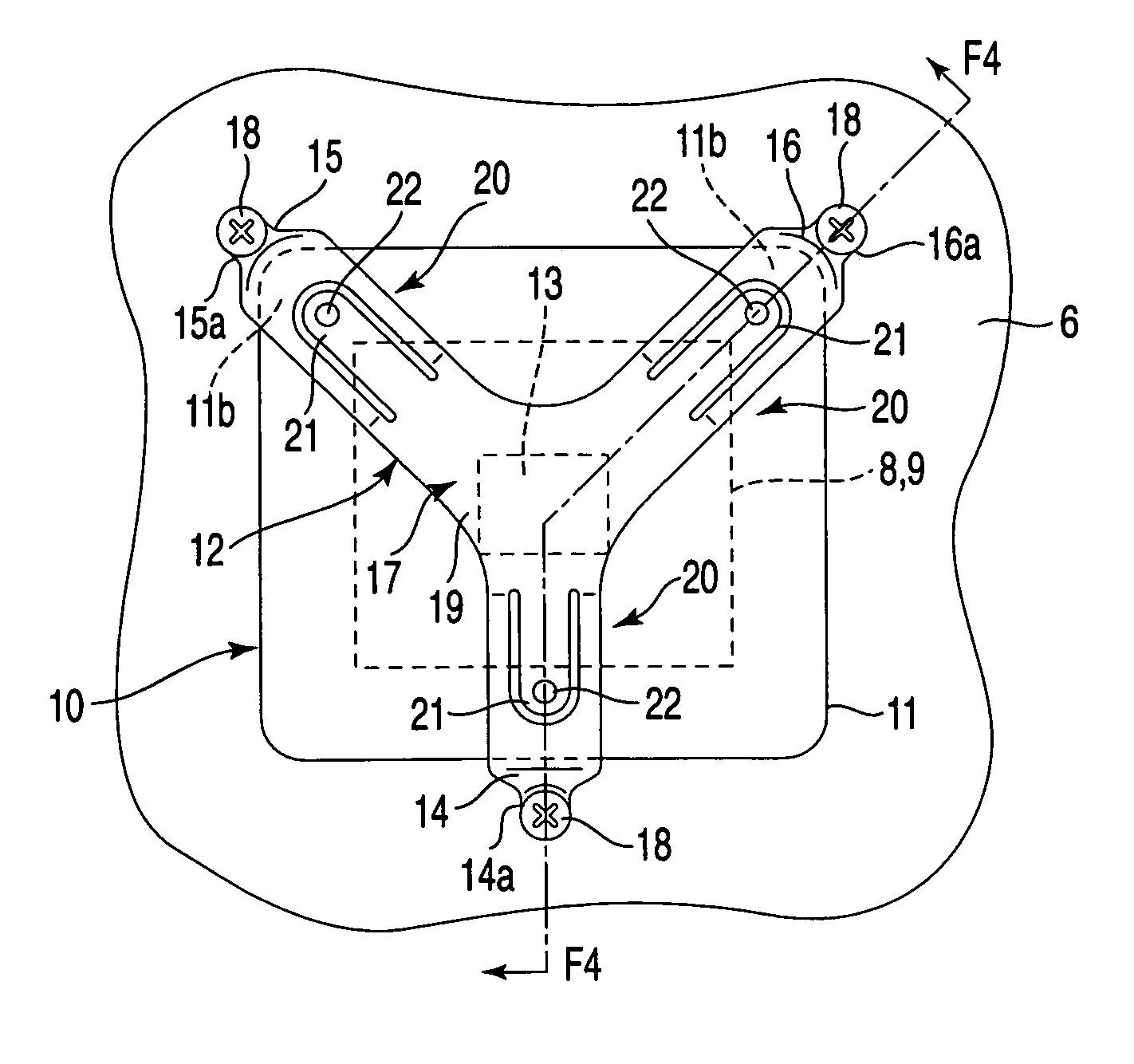
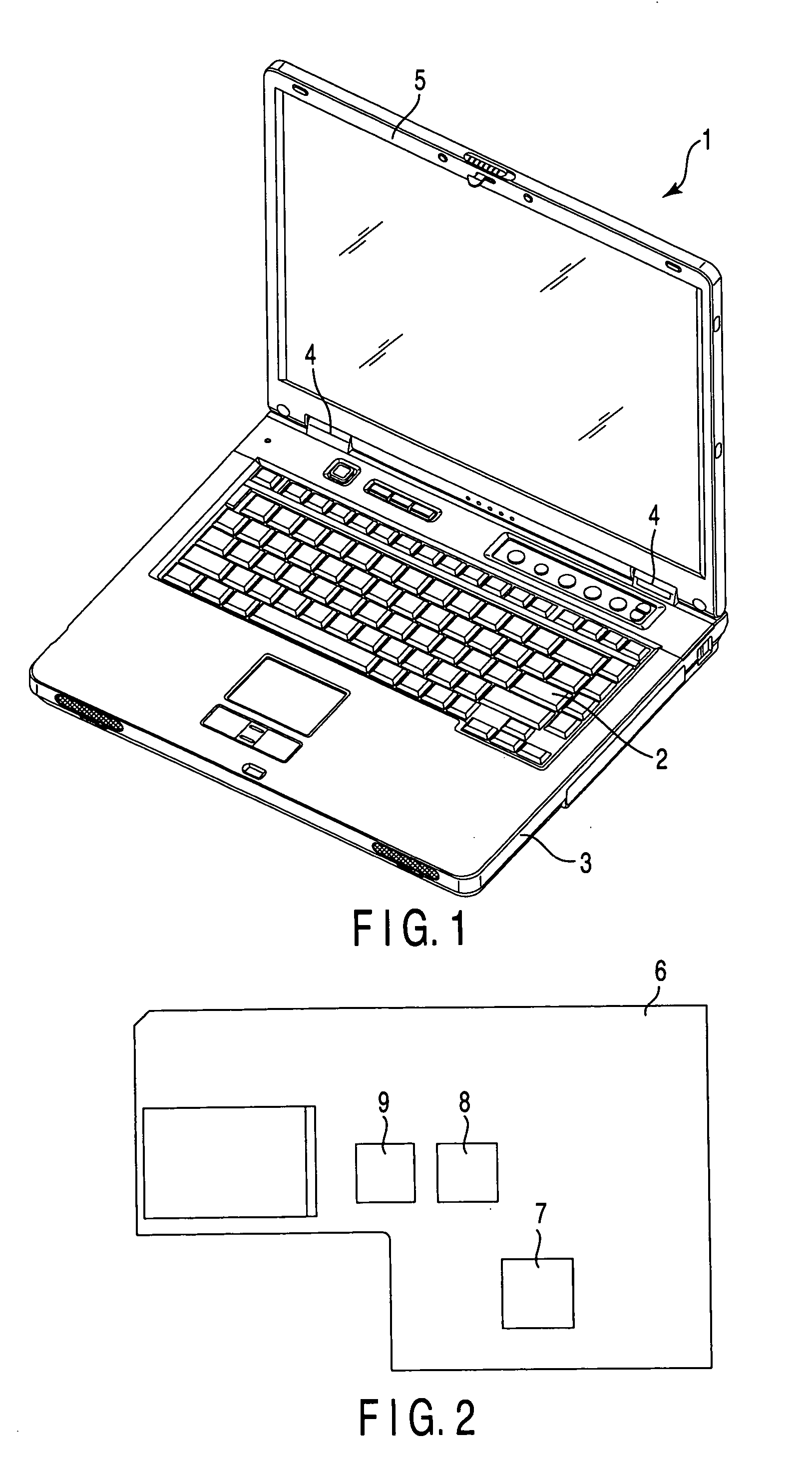
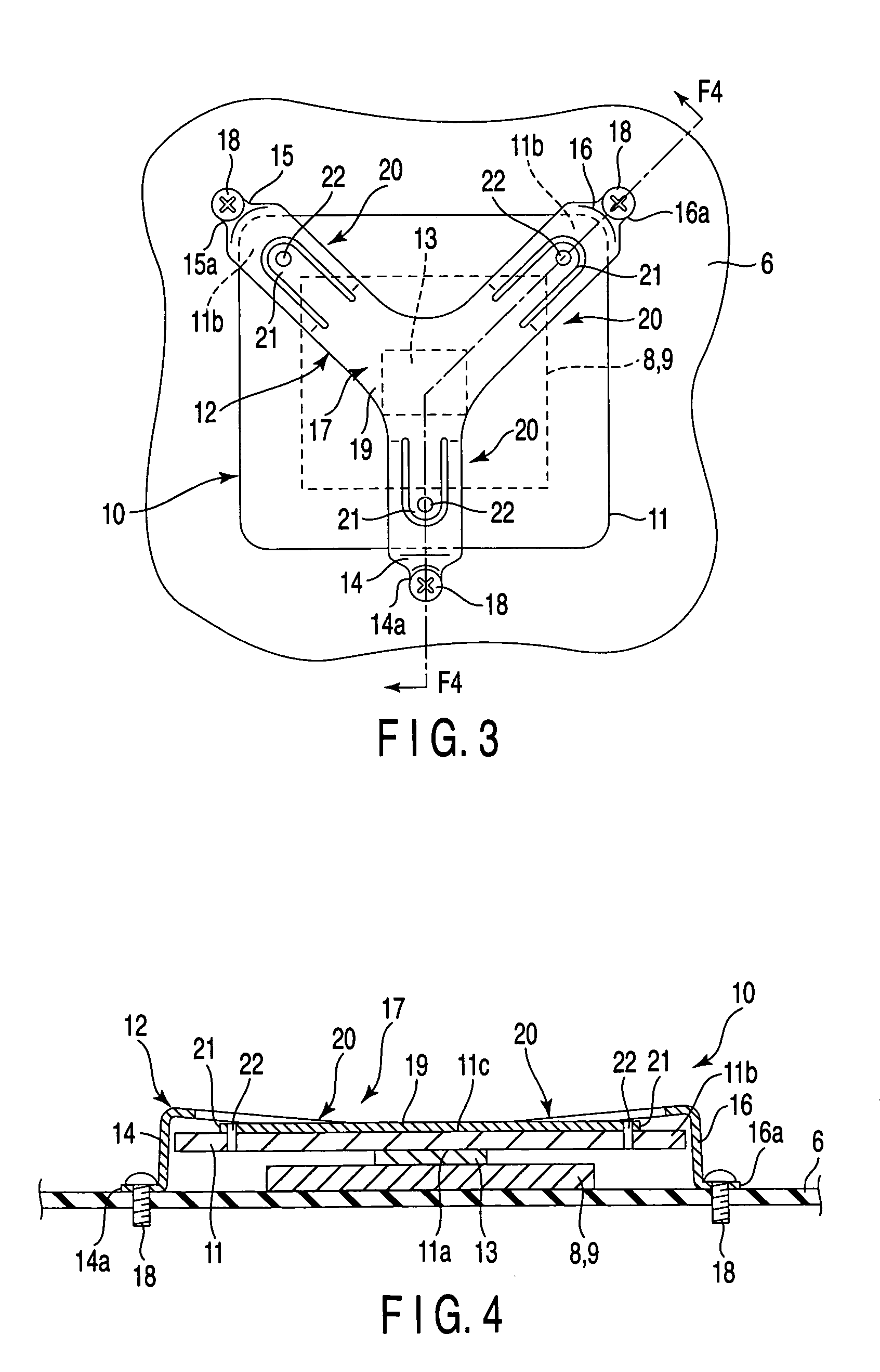
[0026] A notebook PC 1 served as an electronic apparatus of a first embodiment according to the present invention will be explained below with reference to FIG. 1 to FIG. 4. The notebook PC 1 shown in FIG. 1 comprises a housing 3 having a keyboard 2 serving as an input operating portion provided on a top surface thereof, and a display panel 5 coupled to the housing 3 by hinges 4. A substrate 6 shown in FIG. 2 is built in the housing 3. An MPU 7, a bridge 8 and a VGA (Video Graphics Array) 9 are mounted on the substrate 6. The bridge 8 and the VGA 9 are an example of a circuit module which provided in the vicinity of the MPU 7. Load on each of the bridge 8 and the VGA 9 is varied in accordance with variation in load applied to the MPU 7. As the load increases, the amount of heat radiation is also increased. FIG. 2 shows an example of arrangement of the MPU 7, the bridge 8 and the VGA 9 on the substrate 6, and their arrangement is not limited to this.

[0027] To remove the generated hea...

fifth embodiment

[0044] In the fifth embodiment, the radiating unit 10c shown in FIG. 6 is adopted as radiating unit attached to the adjacent circuit modules. The radiating units 10c are fixed on the substrate 6 such that the end portions 14a of the first feet 14 of the radiating units 10c are overlapped.

fourth embodiment

[0045] Thus, the occupied area for attaching each radiating unit 10c on the substrate 6 can be made smaller by fixing at least one of the feet of the radiating unit 10c, i.e. the first foot 14 in this case, at a common position. Similarly to the fourth embodiment, the assembling operation of the radiating unit can be simplified if a radiating unit continuously formed at the end portions such as the end portions 14a of the first feet 14 of the radiating units 10c is provided instead of respectively attaching the radiating unit 10c to the bridge 8 and the VGA 9, and sharing the positions of the fixed feet thereof.

[0046] As shown in FIG. 8, the bridge 8 and the VGA 9 can be arranged side by side, in the vicinity of other adjacent units or modules, by attaching the radiating units 10c to the bridge 8 and the VGA 9. In addition, the wiring between the bridge 8 and the VGA 9, extending to other electronic components mounted on the substrate 6, can easily be arranged.

[0047] Next, a sixth ...


PUM


Abstract

An electronic apparatus includes a housing, a substrate, a bridge, a radiating plate, and a retaining member. The substrate is built in the housing. The bridge has an element portion and is mounted on the substrate. The radiating plate is thermally connected to the element portion. The retaining member has a pressing portion and three feet. The pressing portion is located on an opposite of the element portion about the radiating plate and abuts on the radiating plate. Three feet extend in three directions from the pressing portion and their respective end portions are fixed on the substrate. The retaining member urges the pressing portion toward the radiating plate.

Description

CROSS-REFERENCE TO RELATED APPLICATIONS [0001] This application is based upon and claims the benefit of priority from prior Japanese Patent Application No. 2003-399818, filed Nov. 28, 2003, the entire contents of which are incorporated herein by reference. BACKGROUND OF THE INVENTION [0002] 1. Field of the Invention [0003] This invention relates to an electronic apparatus having a heat conducting member mounted on an element which is mounted on a substrate built in a housing and which generates heat. [0004] 2. Description of the Related Art [0005] A portable computer (PC) is an electronic apparatus in which an MPU (Micro Processing Unit) executing various arithmetic operations is mounted on a substrate built in a housing. In accordance with higher density of circuits and acceleration of the operations, the amount of heat generation in the MPU tends to increase. For this reason, a cooler is provided to positively cool the MPU as seen in, for example, Jpn. Pat. Appln. KOKAI Publicatio...

Claims


Application Information

Patent Timeline
Patent Type & Authority Applications(United States)
IPC IPC(8): G06F1/18G06F1/20H01L23/40H05K7/20
CPCH01L23/4006H01L2924/0002H01L2924/00
Inventor TANAKA, MAKOTO
Owner TOSHIBA CLIENT SOLUTIONS CO LTD
Why Eureka
Try Eureka