Optical tape, optical tape cartridge, optical tape drive, and method for recording data on optical tape

a technology of optical tape and optical tape drive, which is applied in the direction of maintaining the alignment of the head carrier, disposing/mounting the head, instruments, etc., can solve the problems of high recording density, long time that is required to pinpoint the location of data from a recording medium, and lower the level of operating convenience, so as to facilitate the handling of magnetic tape

Inactive Publication Date: 2005-06-02
FUJIFILM CORP +1
View PDF6 Cites 34 Cited by
  • Summary
  • Abstract
  • Description
  • Claims
  • Application Information

AI Technical Summary

Benefits of technology

[0018] With the optical tape cartridge, handling of the magnetic tape can be made easier.
[0019] Thanks to the reference information, the locations where data to be reproduced/recorded is placed are pinpointed for a short time by referring to the index and address included

Problems solved by technology

However, as the recording density is further increased, the time that is required to pinpoint the location of data from a recording medium ends up being longer when the data is searched through the medium or when new data is appended thereon.
This lowers the level of operating convenience.
This may inhibit the high recording density, thereby causing a problem.
Further, optical tape systems are not configured to cause physical contact between a tape and a head as in magnetic tape systems.
On the other hand, within the content of the current technique, a width (pitch) of a data track and a location of the track on an optical tape depend on a system such as an optical tape d

Method used


Image

  • Optical tape, optical tape cartridge, optical tape drive, and method for recording data on optical tape
  • Optical tape, optical tape cartridge, optical tape drive, and method for recording data on optical tape
  • Optical tape, optical tape cartridge, optical tape drive, and method for recording data on optical tape

Examples


Embodiment Construction

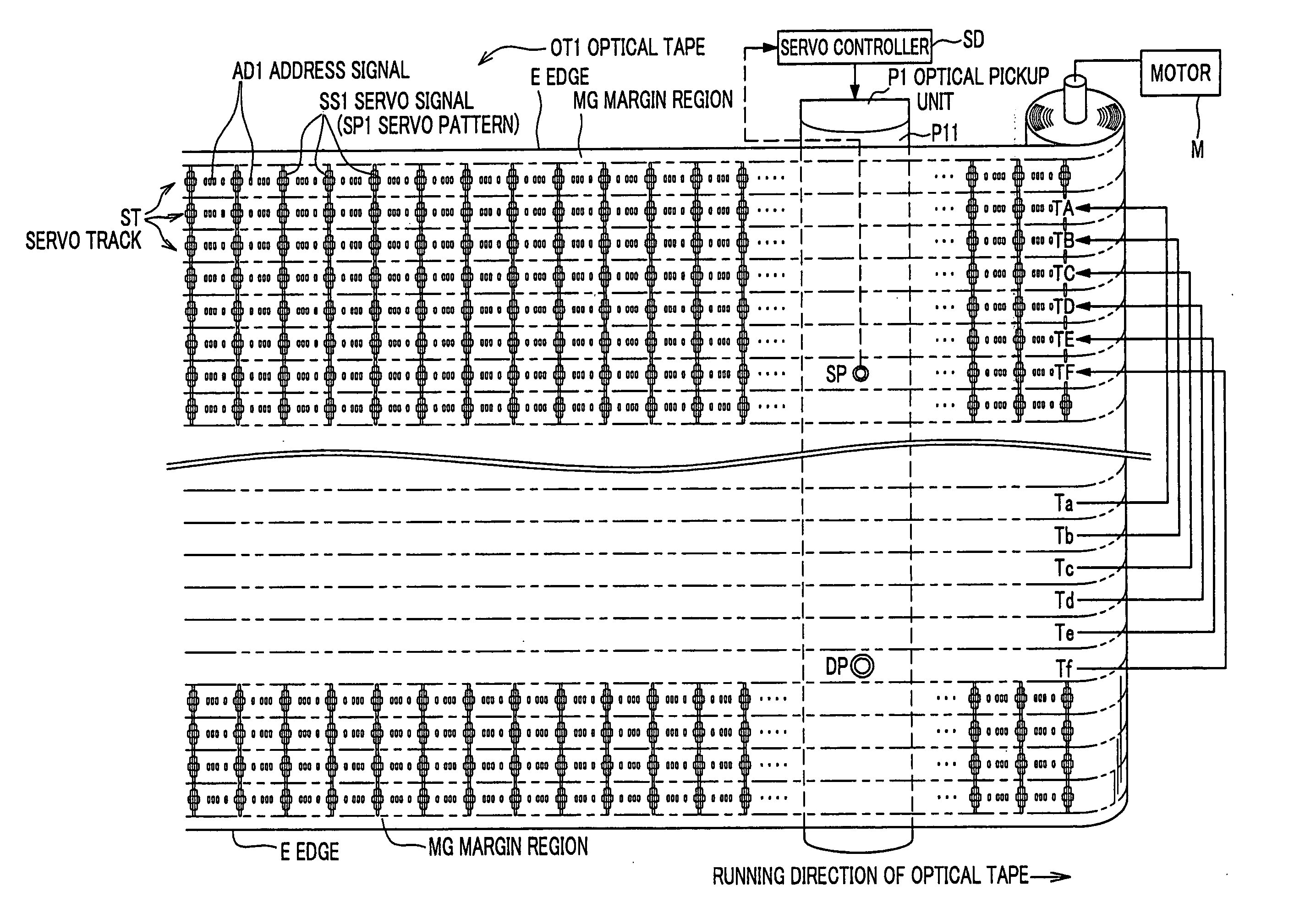
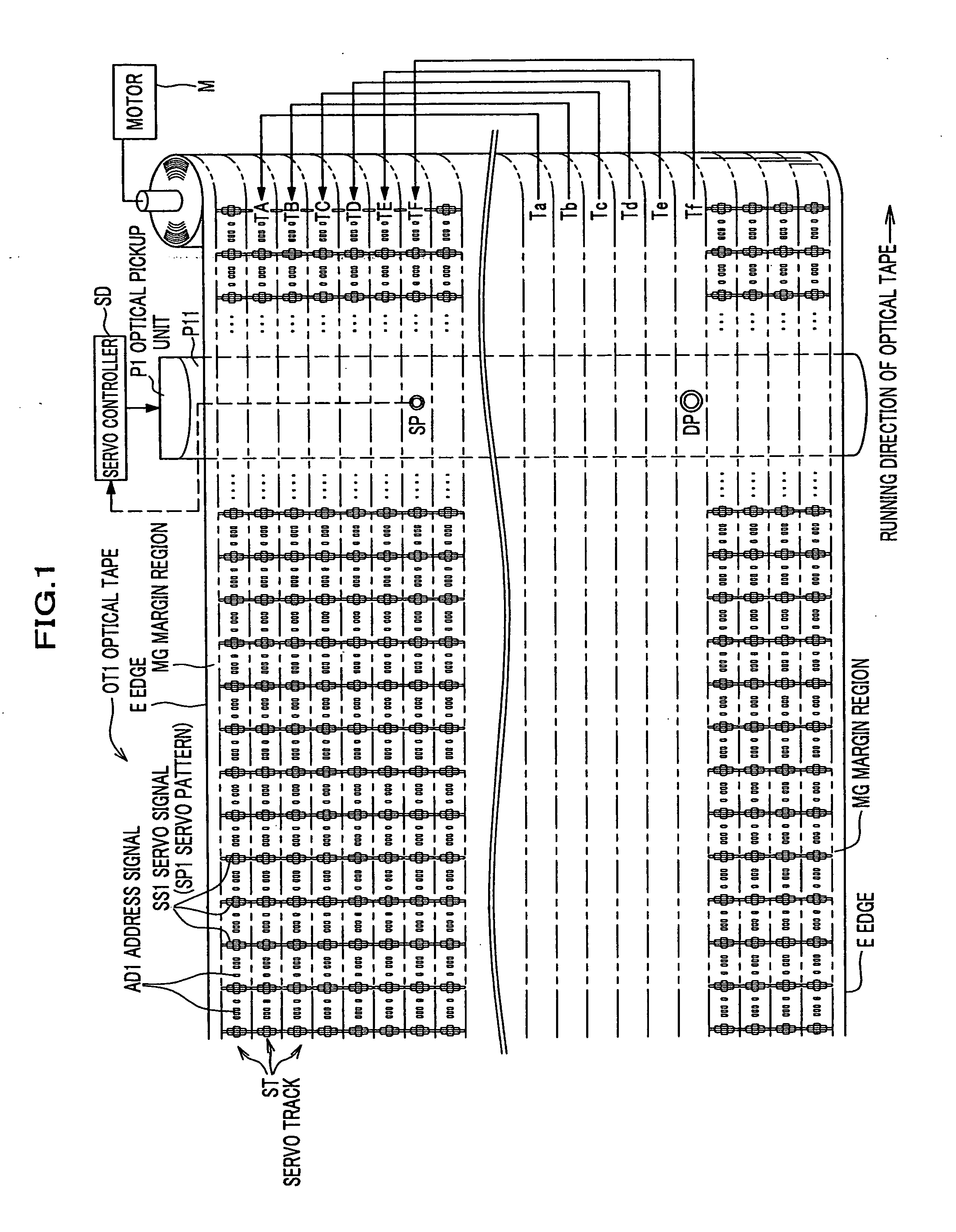
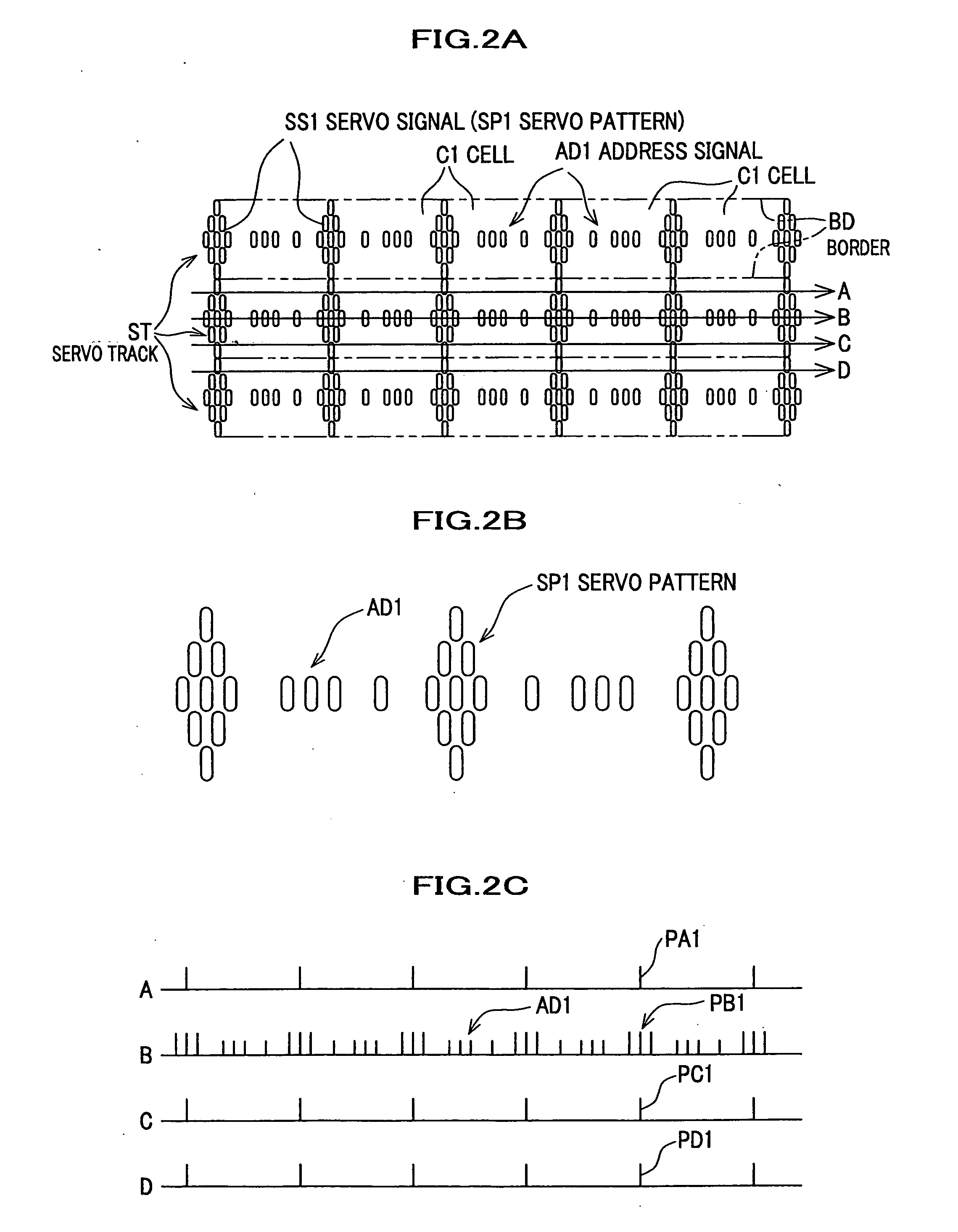
[0046] A description will be given in detail below of an embodiment of the present invention, with reference to accompanying figures as appropriate. FIG. 1 conceptually shows an optical tape according to the embodiment of the present invention, and FIGS. 2A, 2B and 2C show servo signals being recorded on the optical tape according to the embodiment.

[0047] As shown in FIG. 1, an optical tape OT1 according to the embodiment has a surface on which servo signals SS1 are fully recorded by a servo writer (see FIG. 3) which will be described later. Each servo signal SS1 is spanned along a long side of the optical tape OT1, and includes optical-recorded regions, each of which has a predetermined pattern and which are repeatedly recorded lengthwise. Further, these servo signals SS1 are recorded on respective servo tracks ST. On both the long sides of the optical tape OT1, i.e., on both the sides of the group of the servo tracks which are arranged breadthwise adjacent to one another, respect...


PUM


Abstract

Disclosed is an optical tape which contributes to a high recording density, and which achieves an enhanced flexibility in a width of a data track and a data format. The optical tape includes servo tracks being recorded thereon. These servo tracks contain respective servo signals, and are arranged lengthwise and adjacent to one another over a whole of a width or a part of the optical tape. Further, each of the servo tracks includes address signals being recorded thereon at predetermined intervals in isolation from the corresponding servo signals. These address signals indicate their respective locations of corresponding one of the servo tracks and their respective lengthwise locations on the optical tape. In addition, the servo signals are read from the respective servo tracks, and are used to adjust tracking on the optical tape.

Description

BACKGROUND OF THE INVENTION [0001] 1. Field of the Invention [0002] Apparatuses and a method consistent with the present invention relate to an optical tape, an optical tape cartridge, an optical tape drive, and a method for recording data on an optical tape, which are all directed to record information using light. [0003] 2. Description of the Related Art [0004] As the high recording density of information recording media advances, a demand for an accurate tracking technique becomes stronger. To meet this demand, at present, servo-tracking signals (servo signals) are recorded on an information recording medium beforehand, and data is recorded / reproduced on / from the recording medium, while the servo signals are read and the tracking on the medium is then adjusted based on the servo signals read. [0005] However, as the recording density is further increased, the time that is required to pinpoint the location of data from a recording medium ends up being longer when the data is search...

Claims


Application Information

Patent Timeline
IPC IPC(8): G11B23/30G11B5/584G11B7/00G11B7/003G11B7/09G11B7/24009G11B23/36G11B27/10G11B27/32
CPCG11B7/003G11B7/0938G11B2220/90G11B27/323G11B27/107
Inventor SUEKI, MINORUNISHIDA, TETSUJI
Owner FUJIFILM CORP
Why Eureka
Try Eureka