X-ray imaging apparatus and x-ray imaging method
a technology which is applied in the field of x-ray imaging apparatus and x-ray imaging method, can solve the problems of inability to observe the position of the sample, the intensity change caused by the absorption of the sample is extremely small, and it is difficult to perform the fine observation of the sample mainly composed of light elements such as biological soft tissues and organic materials, etc., to achieve the effect of increasing the exposure of x-rays
- Summary
- Abstract
- Description
- Claims
- Application Information
AI Technical Summary
Benefits of technology
Problems solved by technology
Method used
Image
Examples
first embodiment
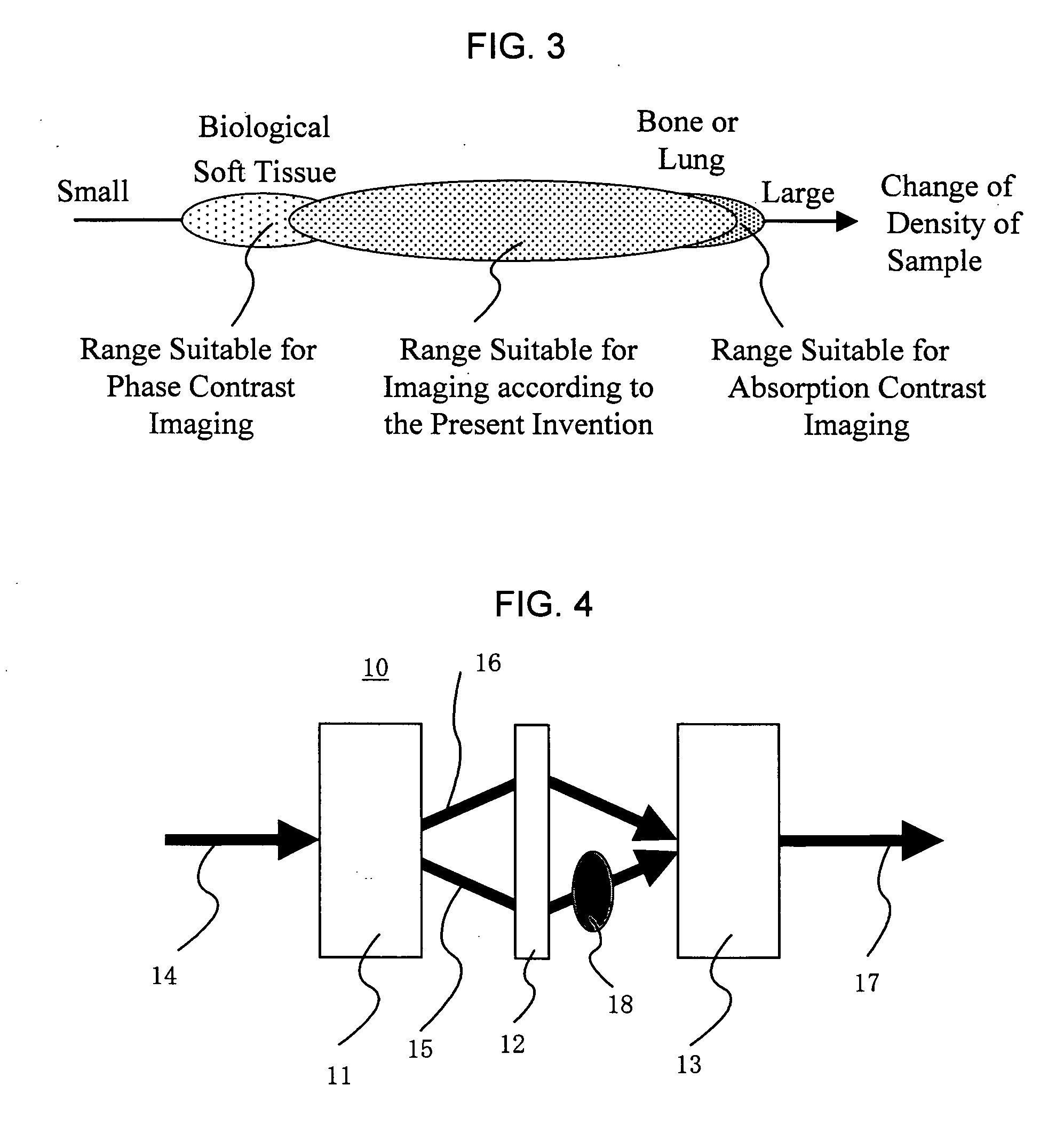
[0047]FIG. 6 is a view showing a constitution of one example of an X-ray imaging apparatus used in the present invention. The present X-ray imaging apparatus comprises an X-ray interferometer 19, a position adjusting mechanism 20 for an X-ray interferometer, a sample holder 21, a sample holder positioning mechanism 22, a phase shifter 23, a phase shifter positioning mechanism 24, an X-ray detector 25, a controller 26, a processing portion 27 and a display unit 28.
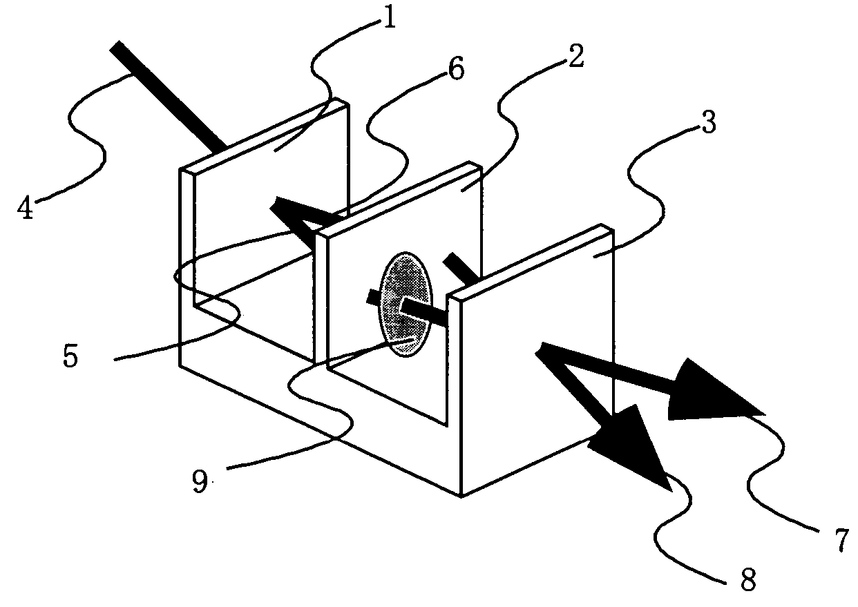
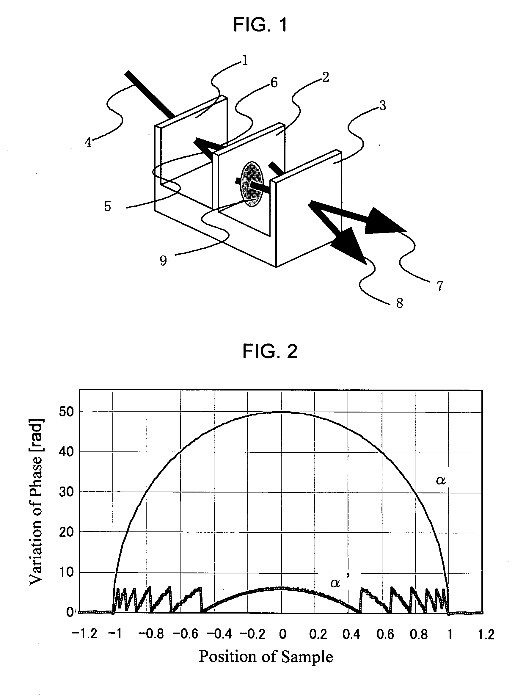
[0048] In this embodiment, a Bonse-Hart interferometer shown in FIG. 1 is used as the interferometer 19. An incident X-ray 29 is split, reflected and combined sequentially by a splitter 30, a mirror 31, and an analyzer 32, to from a first interference beam 32a and a second interference beam 32b in this interferometer. When a sample is placed in an optical path of split one beam by using a sample holder 21 positioned by a sample holder positioning mechanism 22, X-ray intensity, phase and a transmission direction of an X-ray...
second embodiment
[0067] In the embodiment 1, the change in the amplitude and the phase of the interference beam caused by the sample has been detected by using the fringe scanning method. To perform this method, three sheets of the interference images which are in phase relationships different from each other are required at least. Because of its long measurement time, therefore it is difficult to apply this method to the dynamical observations. Accordingly, the embodiment using the Fourier transformation method in place of the fringe scanning method will be shown in this case. In the Fourier transformation method, the change in the amplitude and the phase can be obtained by one sheet of the interference image, therefore the measuring time can significantly be shortened. On the other hand, the spatial resolution is slightly lowered as compared with that of the fringe scanning method, because the spatial resolution is determined mainly by an interval of Moire-image interference fringes as described l...
third embodiment
[0071] In the embodiments 1 and 2, only the image (transmitted image) passing through the sample can be measured. An embodiment capable of observing the inside of the sample nondestructively will be shown. FIG. 12 is a block diagram showing a constitution of the embodiment 3.
[0072] The apparatus is similar to that of the embodiments 1 and 2 excluding a sample holder 33 and a sample holder rotating mechanism 34. The sample is fixed to the sample holder 33, and rotated in a direction perpendicular to an optical axis by the sample holder rotating mechanism 34. In order to reduce an influence by the shape of the sample, the inside of the sample holder 33 may be filled up with a liquid having the density close to the density of the sample.
[0073] In the embodiment 3, the measurement is performed by the procedure shown in FIG. 13.
[0074] (1) Similar to the procedure of the first half of FIG. 7, the step 1201 (measurement of background data), the step 1202 (placing the sample in the optic...
PUM
 Abstract
Description
Claims
Application Information
 - R&D
- Intellectual Property
- Life Sciences
- Materials
- Tech Scout
- Unparalleled Data Quality
- Higher Quality Content
- 60% Fewer Hallucinations
Browse by: Latest US Patents, China's latest patents, Technical Efficacy Thesaurus, Application Domain, Technology Topic, Popular Technical Reports.
© 2025 PatSnap. All rights reserved.Legal|Privacy policy|Modern Slavery Act Transparency Statement|Sitemap|About US| Contact US: help@patsnap.com


