Discrete passage diffuser

a diffuser and centrifugal compressor technology, applied in the direction of wind turbines, liquid fuel engines, wind turbines with parallel air flow, etc., can solve the problems of affecting the efficiency of the compressor and therefore the overall aerodynamic performance of the compressor, and failing to provide such an ideal match with the exit angle of the impeller fluid

Inactive Publication Date: 2005-06-02
PRATT & WHITNEY CANADA CORP
View PDF15 Cites 20 Cited by
  • Summary
  • Abstract
  • Description
  • Claims
  • Application Information

AI Technical Summary

Benefits of technology

[0006] It is an object of the present invention to provide a diffuser capable of improving compressor efficiency.
[0007] It is a further object of the present invention to provide an improved incidence match between the impeller exit air angles and the diffuser leading edge angles.

Problems solved by technology

One cause of centrifugal compressor pressure losses, which negatively affect the compressor efficiency and therefore the overall compressor aerodynamic performance, is any mismatch between the impeller exit flow angles and the inlet angles of the diffuser.
Traditionally used diffuser pipes having a circular cross-section form generally oval diffuser passage leading edges, which fail to provide such an ideal match with the impeller fluid exit angles.

Method used


Image

  • Discrete passage diffuser
  • Discrete passage diffuser
  • Discrete passage diffuser

Examples


Embodiment Construction

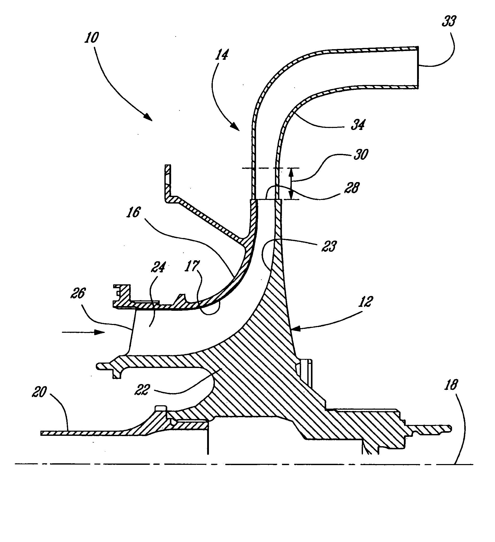
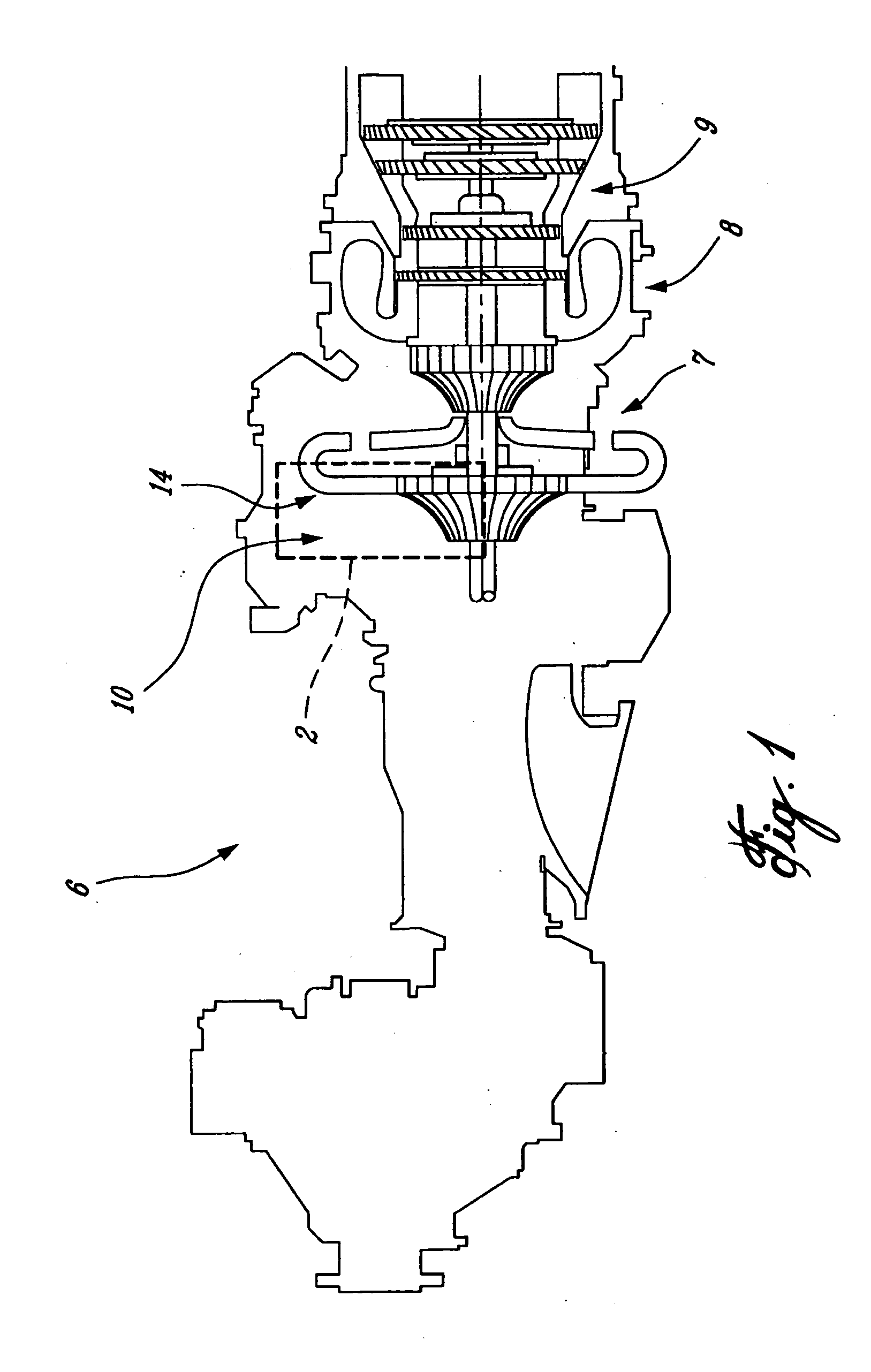
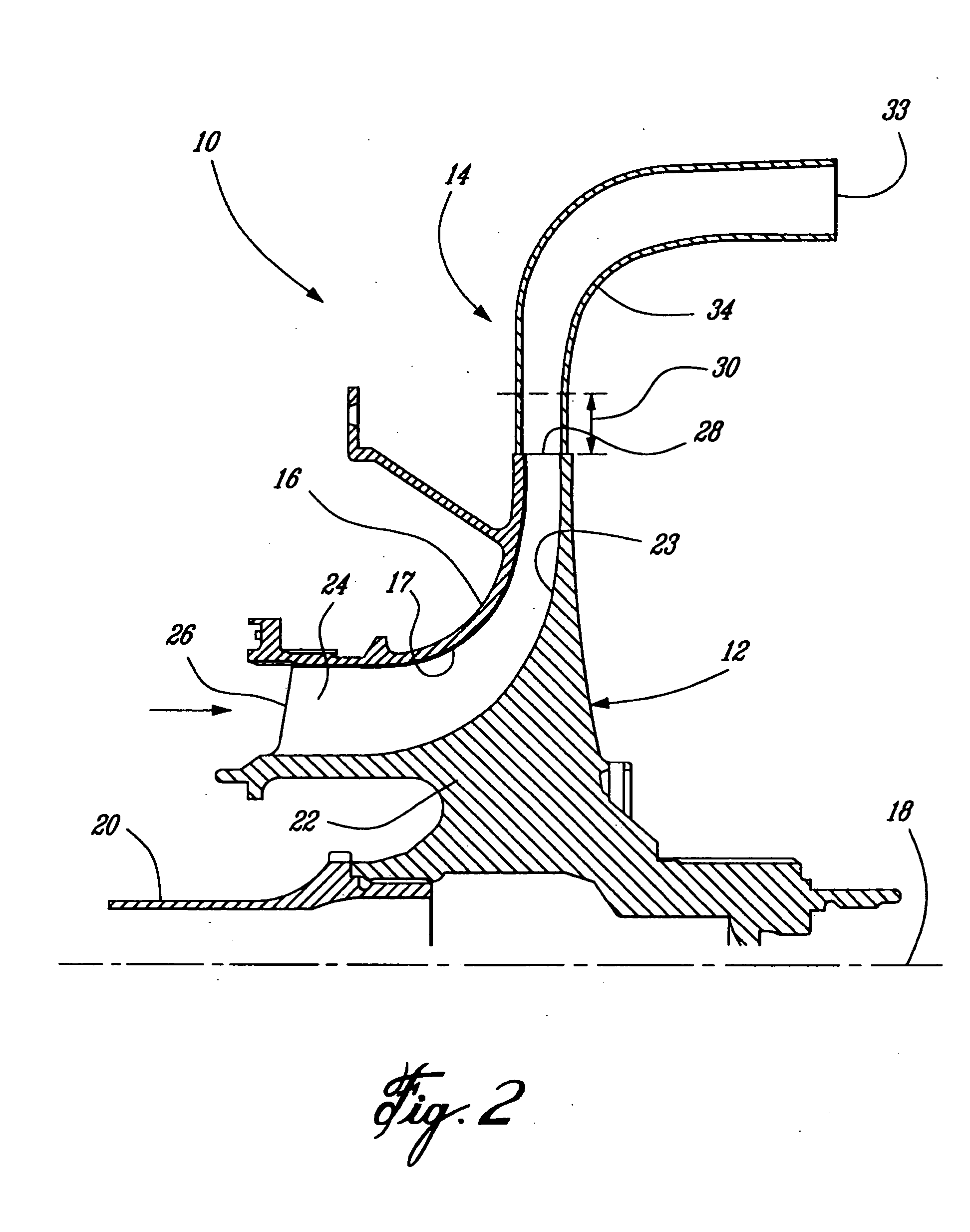
[0017] Referring to FIG. 1 showing a generic gas turbine engine 6, one application of the present invention, having generally at least a compressor portion 7, a combustion portion 8, and a turbine portion 9. The compressor portion 7 includes at least a centrifugal compressor assembly 10. The gas turbine engine can comprise a turboprop, turbofan or turboshaft engine. While such a gas turbine engine is shown and represents one possible application for a diffuser 14 of the present invention, such a diffuser is equally applicable in any other application having a centrifugal compressor, including but not limited to automotive turbochargers, air conditioning compressors and the like.

[0018] Referring now to FIG. 2, the centrifugal compressor assembly 10 comprises generally an impeller 12 and the diffuser 14. The impeller 12, fixed to a central shaft 20, rotates about a central axis 18 within a stationary impeller shroud 16. The impeller 12 comprises a central hub portion 22 and a plurali...


PUM


Abstract

A centrifugal compressor includes an impeller and a diffuser. The impeller has an inner integral hub with vanes thereon, is adapted to rotate within an outer shroud about a central longitudinal axis, and has a defined hub-to-shroud distribution of fluid exit angles. The diffuser, downstream from the impeller, comprises a plurality of circumferentially spaced discrete passages at least partially defining fluid paths through the diffuser, and angled such that adjacent discrete passages intersect each other to form an annular semi-vaneless diffuser inlet space. The discrete passages downstream of the semi-vaneless space each have an inlet therefrom and an outlet with a greater cross-sectional area than the inlet. The intersection of the annular semi-vaneless space and each discrete passage defines a leading edge thereof. Each discrete passage is defined by a wall bounding a cross-sectional area, the wall comprising at least a first substantially rectilinear portion and a second opposed convexly curved portion; the first substantially rectilinear portion is adjacent the hub of the impeller and the second opposed convexly curved portion is adjacent the outer shroud. The leading edge of each discrete diffuser passage provides a close incidence angle match with the fluid exit angles of the impeller.

Description

RELATED APPLICATIONS [0001] This is a continuation of International Patent Application No. PCT / CA03 / 00526 filed Apr. 10, 2003, which claims benefit of U.S. patent application Ser. No. 10 / 140,101 filed on May 8, 2002, the contents of both are incorporated herein by reference.TECHNICAL FIELD [0002] The present invention relates generally to centrifugal compressors, and in particular, to a diffuser for a centrifugal compressor. BACKGROUND OF THE INVENTION [0003] Centrifugal compressors have a wide variety of industrial and aeronautical applications, including gas turbine engines, fluid pumps and air compressors. Centrifugal compressors generally consist of at least two main components: an impeller and a diffuser. [0004] Pipe diffusers, generally having circumferentially spaced frustro-conical discrete passages, are commonly used to perform these functions. Typically, the radially extending passages are angled from the radial direction such that their center lines are all tangent to a s...

Claims


Application Information

Patent Timeline
Patent Type & Authority Applications(United States)
IPC IPC(8): F01D9/04F02C3/08F04D29/44
CPCF01D9/045F04D29/444F04D29/441F01D9/048F05D2250/52
Inventor ROBERTS, DOUGLAS ALLANLEBLANC, ANDRE DENISKACKER, SURESH CHANDRATOWNSEND, PETER RALPHSASU, IOAN
Owner PRATT & WHITNEY CANADA CORP
Why Eureka
Try Eureka