Fuel cell power generation device and fuel cell power generation method

Inactive Publication Date: 2005-06-02
KK TOSHIBA
View PDF2 Cites 22 Cited by
  • Summary
  • Abstract
  • Description
  • Claims
  • Application Information

AI Technical Summary

Benefits of technology

[0011] It is hence an object of the present invention to provide a fuel cell power generation device and a fuel cell power generation method capable of obtaining a stable power generation output for a long period of time.
[0014] According to the invention, a stable power generation output can be obtained for a long period of time.

Problems solved by technology

However, the above-mentioned direct methanol fuel cell power generation device has its own problems.
Other causes of output drop in continuous operation include fuel not reaching a catalyst layer due to physical clogging of produced substances on a diffusion layer such as carbon paper having the catalyst layer for composing a membrane electrode assembly (MEA), and blocking of supply of fuel by direct deposits on the fuel passage.
Further, by prolonged continuous operation, not only output drop, but also decline of fuel efficiency and the like are induced, and by continuous operation for only several hours, ultimately, it is known that the power generation capacity is lowered to 90% or less of the initial level.
Hence, the merit of continuous operation without recharging cannot be utilized sufficiently.

Method used


Image

  • Fuel cell power generation device and fuel cell power generation method
  • Fuel cell power generation device and fuel cell power generation method
  • Fuel cell power generation device and fuel cell power generation method

Examples


Embodiment Construction

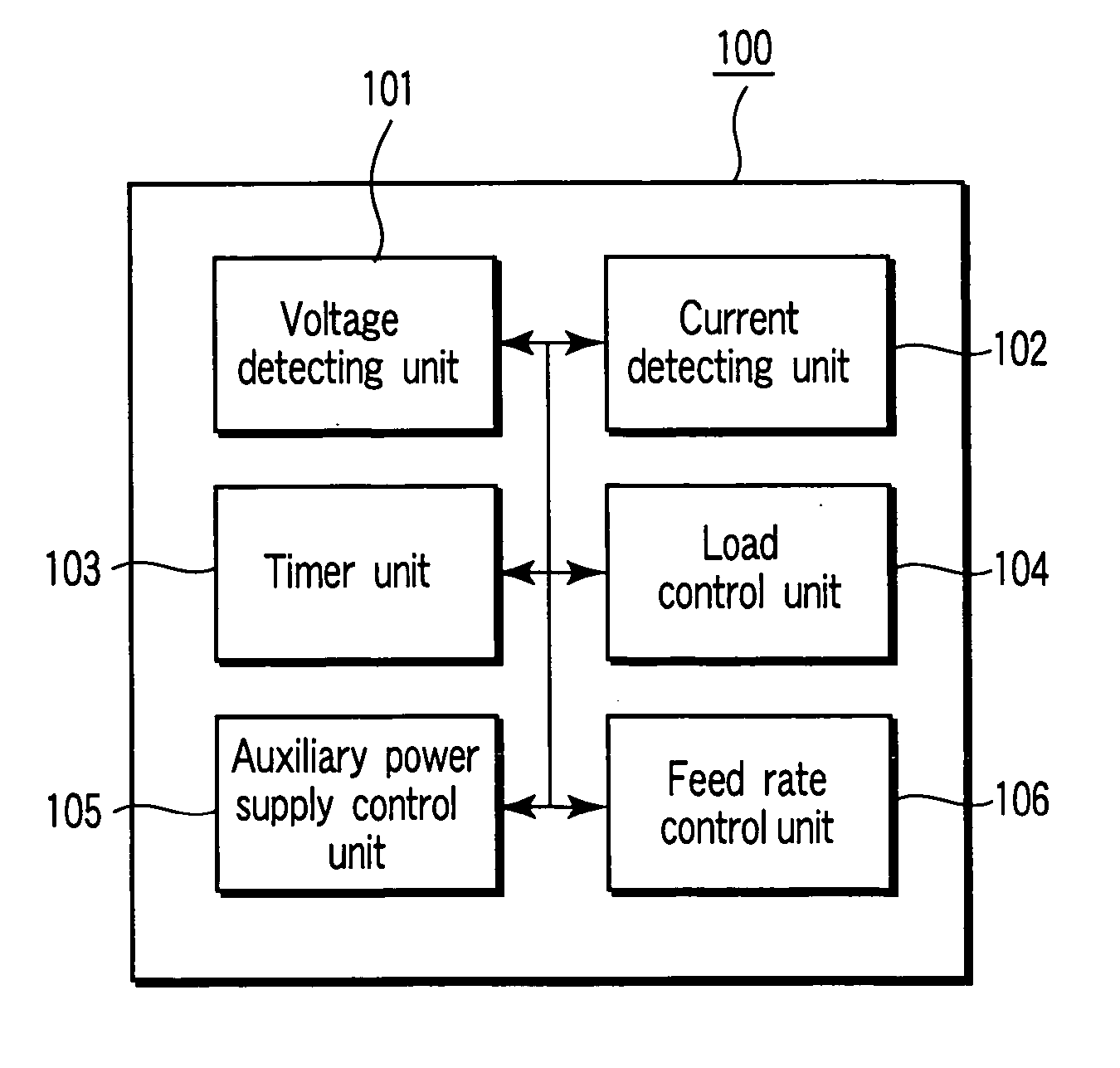
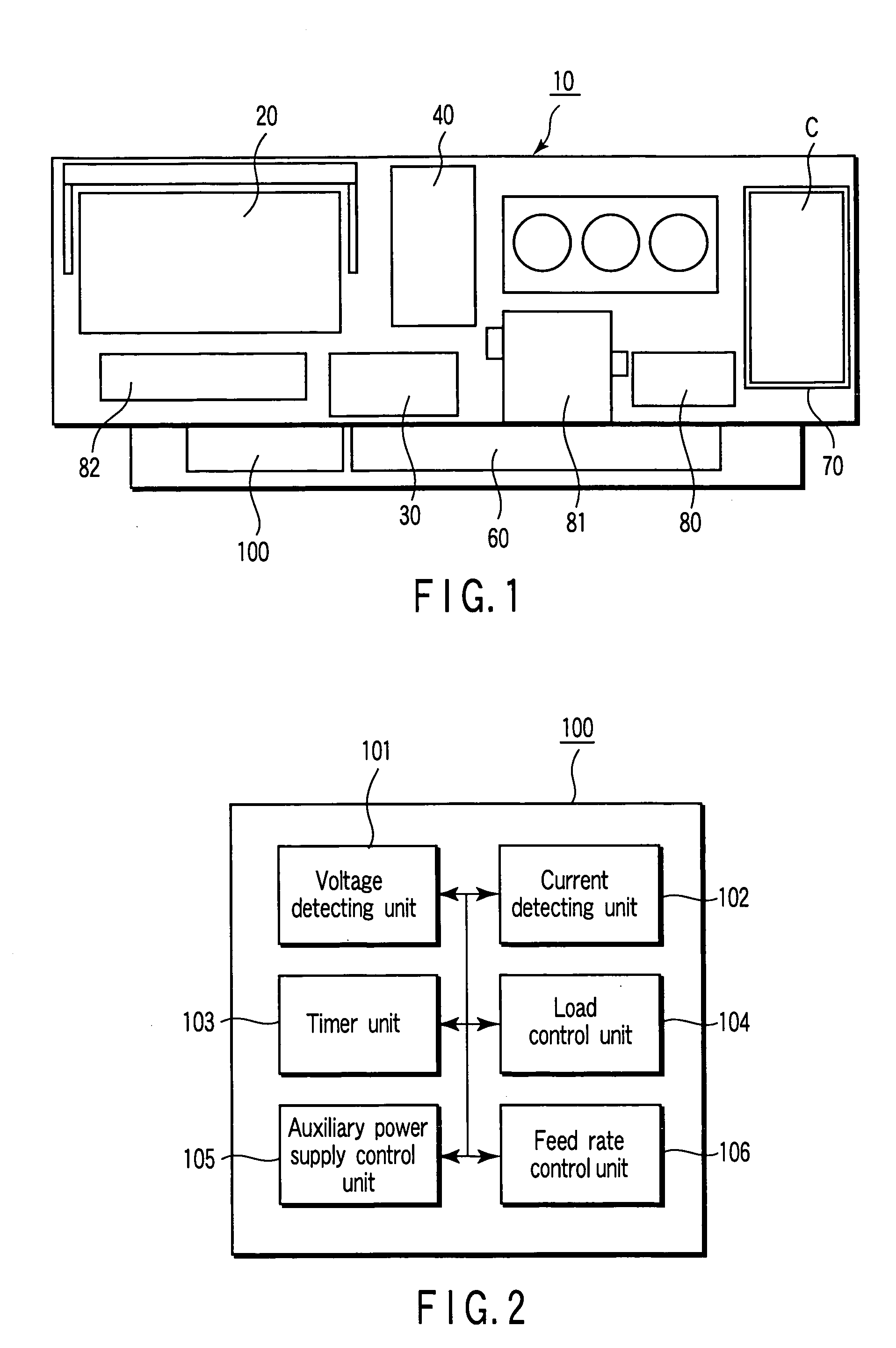
[0019]FIG. 1 is a block diagram of a schematic configuration of a fuel cell power generation device 10 according to an embodiment of the present invention. The fuel cell power generating device 10 comprises a DMFC electromotive device (electromotive unit) 20 for generating an electromotive force by chemical reaction between an aqueous methanol solution of fuel and air (oxygen) by way of an electrolyte film, a liquid feed pump (liquid fuel feed unit) 30 for supplying the aqueous methanol solution (liquid fuel) to the DMFC electromotive device 20, an air feed pump (gas feed unit) 40 for supplying air (oxidizer), a secondary battery unit (auxiliary power supply) 50, an output unit 60 for outputting from an output terminal (not shown), a cartridge unit 70 to which a fuel cartridge C described later is detachably connected, and a DMFC control unit (control unit) 100 for controlling power generation operation of the DMFC electromotive device 20 by controlling the action of these component...


PUM


Abstract

A fuel cell power generating device comprises an electromotive unit which is formed by stacking of membrane electrode assembly which is enclosing an electrolyte film with an anode electrode and a cathode electrode and generates an electric power, a liquid fuel feed unit which supplies a liquid fuel to the anode electrode, a gas feed unit which supplies an oxidizer gas to the cathode electrode, a control unit which controls at least either the gas feed rate control for adjusting the feed rate of the oxidizer gas by the gas feed unit or the liquid fuel control for adjusting the feed rate of the liquid fuel by the liquid feed unit, at the time of satisfying either the condition in which the electromotive force of the electromotive unit is lower than a predetermined reference value, or the condition in which the predetermined time interval passes.

Description

CROSS-REFERENCE TO RELATED APPLICATIONS [0001] This application is based upon and claims the benefit of priority from prior Japanese Patent Application No. 2003-385426, filed Nov. 14, 2003, the entire contents of which are incorporated herein by reference. BACKGROUND OF THE INVENTION [0002] 1. Field of the Invention [0003] The present invention relates to a fuel cell power generation device and a fuel cell power generation method using liquid fuel such as methanol or an aqueous methanol solution as the fuel, and more particularly to a technology capable of obtaining a stable power generation output for a long period of time. [0004] 2. Description of the Related Art [0005] A direct methanol fuel cell power generation device using methanol as fuel is designed to generate electric power by supplying an aqueous methanol solution to an anode electrode (fuel electrode) and air (oxygen) to a cathode electrode (oxidant electrode). By generating electric power, an oxidation reaction of metha...

Claims


Application Information

Patent Timeline
IPC IPC(8): H01M8/10H01M8/04H01M8/06
CPCH01M8/04089H01M8/04186Y02E60/523H01M8/1011H01M8/0662Y02E60/50
Inventor HARADA, YASUHIROSHIBUYA, NOBUO
Owner KK TOSHIBA
Why Eureka
Try Eureka