
Device for automatically mounting and dismantling tools on a robot

a robot and tool technology, applied in the field of robot automatically mounting and dismantling tools, can solve the problem that the device occupies a lot less space around the robo

Inactive Publication Date: 2005-06-02
SN DETUDE & DE CONSTR DE MOTEURS DAVIATION S N E C M A
View PDF17 Cites 6 Cited by
  • Summary
  • Abstract
  • Description
  • Claims
  • Application Information

AI Technical Summary

Benefits of technology

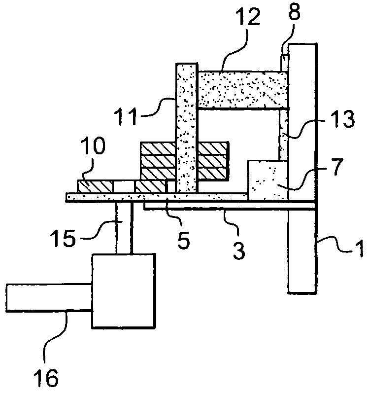
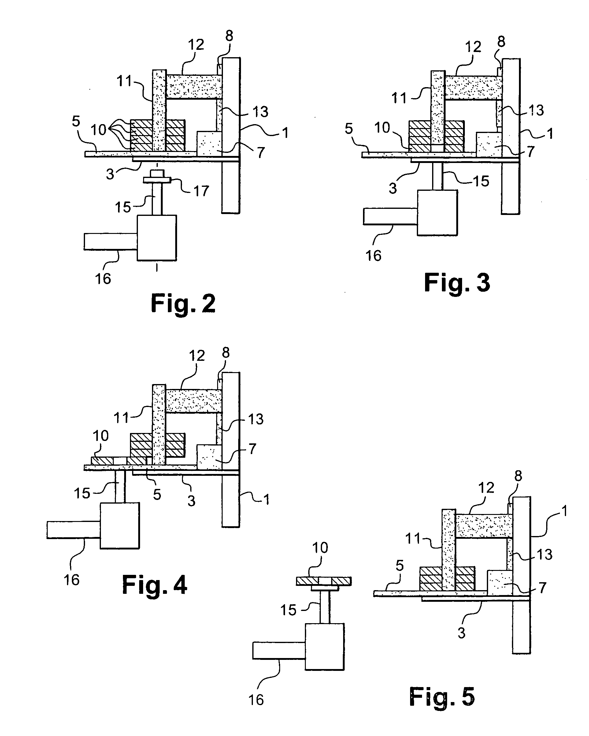
[0013] In the device according to the invention, the stacked tools are centered precisely on the support surface using the rod engaged in their axial orifices, irrespective of any deformations of these tools owing to their flexibility (in the case of brushes). Such precise centering eliminates the risk of failure of the automatic mounting on the robot. Moreover, the storage of the tools in vertical stacks means the device takes up much less space around the robot.
[0016] When ten or so devices according to the invention are arranged around the robot, the ten corresponding sensors can be linked to the robot without the need for the latter to have an input / output extension board. This results in a significant cost saving.

Problems solved by technology

Moreover, the storage of the tools in vertical stacks means the device takes up much less space around the robot.

Method used


Image

  • Device for automatically mounting and dismantling tools on a robot
  • Device for automatically mounting and dismantling tools on a robot
  • Device for automatically mounting and dismantling tools on a robot

Examples


Embodiment Construction

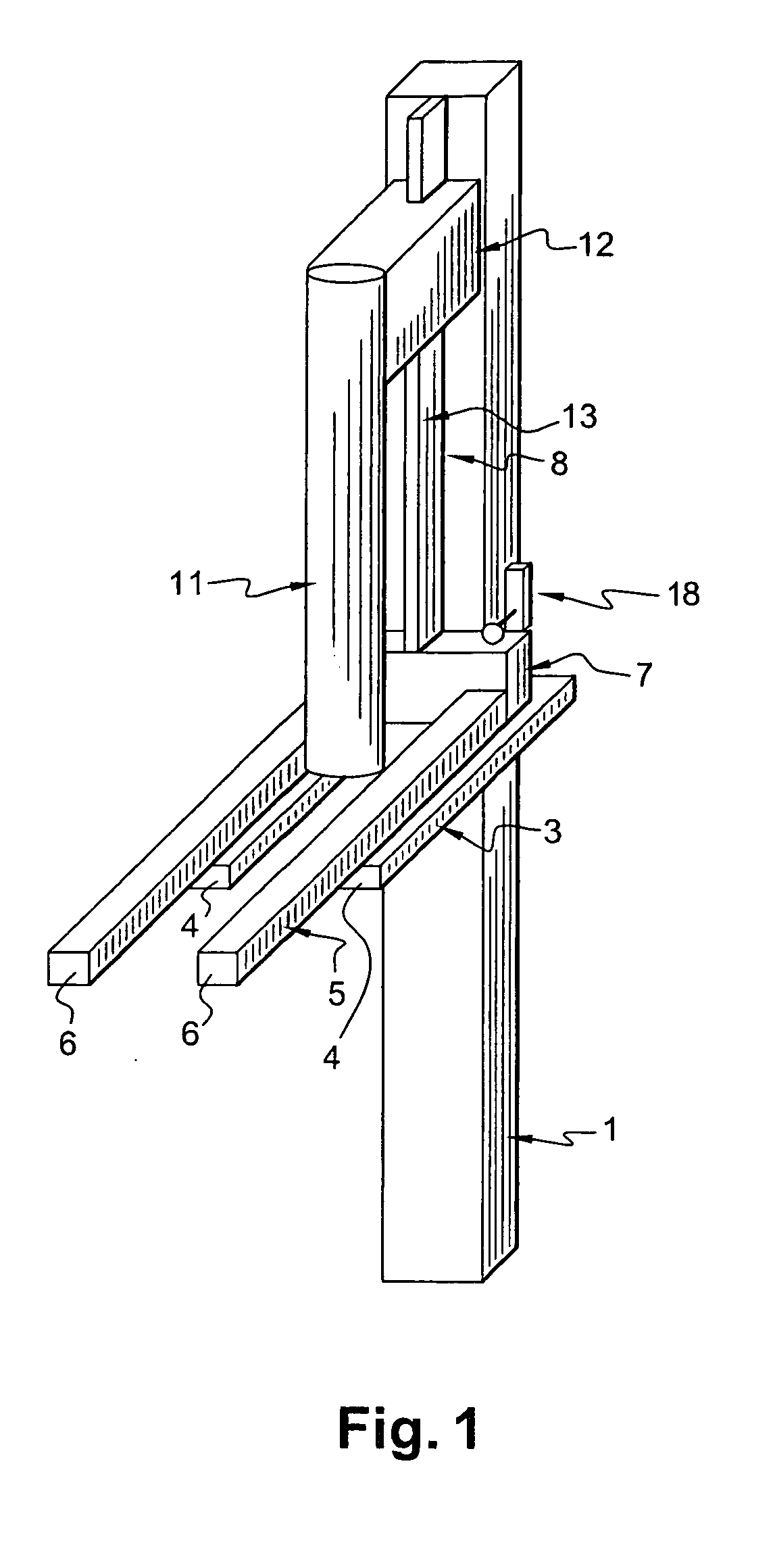
[0036] Referring first to FIG. 1, this schematically shows an embodiment of the device according to the invention. This device is essentially intended for the storage of fresh tools such as brushes or grinding wheels, and is designed to allow the automatic mounting and dismantling of these tools on a robotic arm having a pin for rotating a tool.

[0037] It comprises storage means comprising a vertical upright 1, which is fastened to the floor or a wall by appropriate means, on which is fixedly mounted a horizontal support 3 in the shape of a fork, comprising two parallel arms 4 extending in the same direction from the vertical upright 1 and separated from one another by a distance which is smaller than the diameter of the tools intended to be stored in the device according to the invention, and larger than the diameter of the pin of the robotic arm on which these tools must be mounted, as will be seen more clearly below.

[0038] Another support 5, also fork-shaped, is mounted so as to...


PUM


Abstract

Device for automatically mounting and dismantling tools (10) on a robot (16), comprising means (1) for storing a number of identical fresh tools (10) and means (11) for centering one of these tools (10) in a position for automatic mounting on the robot (16), each tool (10) comprising an axial orifice for mounting on a rotating pin (15) provided on the robot (16).

Description

BACKGROUND OF THE INVENTION [0001] The present invention relates to a device for automatically mounting and dismantling tools on a robot with a robotic arm. [0002] The tools mounted on a robotic arm must regularly be replaced to change the type of tool used, its characteristics or simply to replace a worn tool with a fresh one. [0003] The types of tool concerned by the invention comprise an axial orifice for mounting on a pin for rotating the tool, in particular brushes and grinding wheels. DESCRIPTION OF THE PRIOR ART [0004] In the current state of the art, the various types of tools are stored on slides terminating at their lower end in a V-shaped part for centering a tool in a position for automatic mounting on a robotic arm. The lower end of the slide bears sensors to determine the position of the tool mounting orifice. [0005] For each type of tool, there is also a station for depositing and retrieving partially worn tools, this station also having sensors providing information ...

Claims


Application Information

Patent Timeline
Patent Type & Authority Applications(United States)
IPC IPC(8): B25J15/04B23Q3/155B23Q7/10B24B45/00B27B5/30
CPCB23Q3/15526B23Q7/103Y10T483/179Y10S483/901Y10T483/17B27B5/30B23Q3/15536
Inventor NAVAR, PIERRE
Owner SN DETUDE & DE CONSTR DE MOTEURS DAVIATION S N E C M A
Learn More