Intravenous catheter and insertion device
- Summary
- Abstract
- Description
- Claims
- Application Information
AI Technical Summary
Benefits of technology
Problems solved by technology
Method used
Image
Examples
Embodiment Construction
[0017] For a detailed description of the preferred embodiment the reader is referred to the appended figures in which like components are given like numerals for ease of reference.
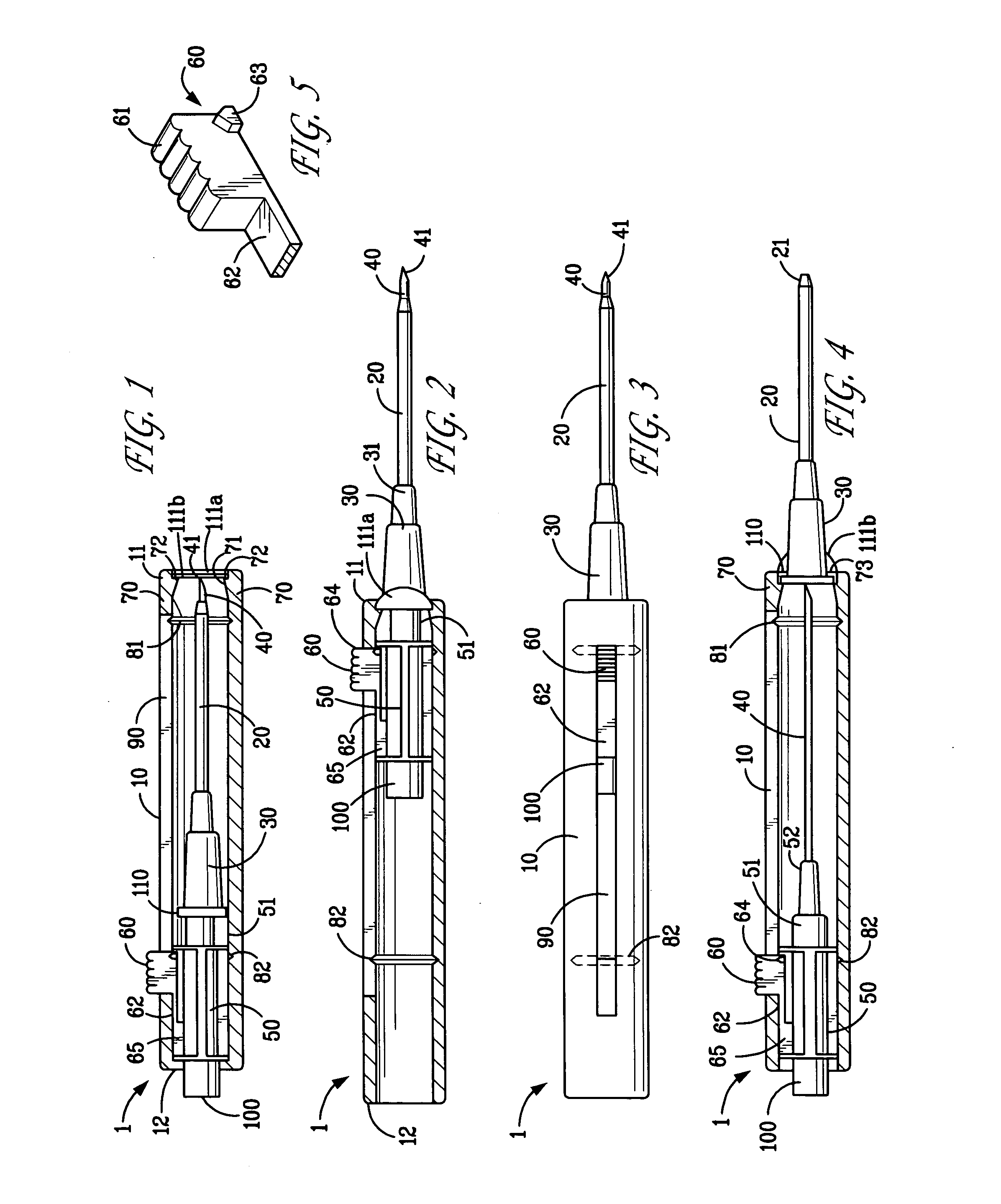
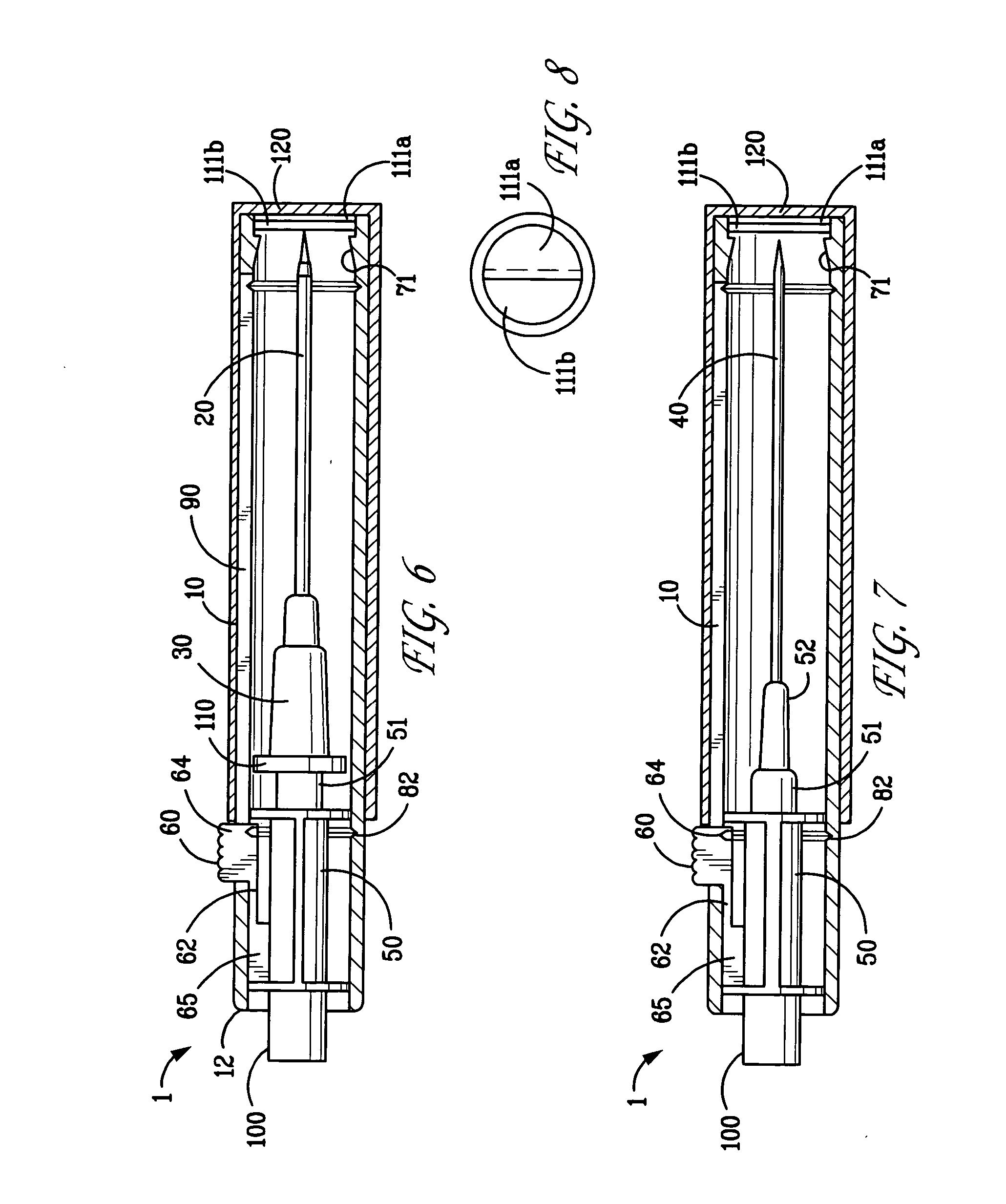
[0018]FIG. 1 generally shows a catheter insertion device 1 having a hollow cylindrical barrel 10 of semi-rigid plastic material. The barrel 10 may be tapered slightly at the insertion end for ease of use. For orientation purposes the barrel 10 is defined as having an insertion end 11 and a distal end 12. A flexible catheter 20 is snugly fit about an insertion needle 40 and both mounted on a carrier 50 which is slidably mounted within the barrel 10. In FIG. 6 the device is depicted as proposed to be shipped with the carrier 50, needle 40 and catheter 20 withdrawn into barrel 10 and a removable cap 120 secured about the insertion end. A resealable closure comprising 111A and 111B is shown near the insertion end. Shipment will be in a sterile package (not shown). In this configuration no protective sheath ab...
PUM
 Abstract
Description
Claims
Application Information
 - R&D
- Intellectual Property
- Life Sciences
- Materials
- Tech Scout
- Unparalleled Data Quality
- Higher Quality Content
- 60% Fewer Hallucinations
Browse by: Latest US Patents, China's latest patents, Technical Efficacy Thesaurus, Application Domain, Technology Topic, Popular Technical Reports.
© 2025 PatSnap. All rights reserved.Legal|Privacy policy|Modern Slavery Act Transparency Statement|Sitemap|About US| Contact US: help@patsnap.com


