Fuel injection valve for diesel engine

Inactive Publication Date: 2005-06-09
YANMAR CO LTD
View PDF6 Cites 36 Cited by
  • Summary
  • Abstract
  • Description
  • Claims
  • Application Information

AI Technical Summary

Benefits of technology

[0012] According to the invention defined in claim 1, in a diesel engine having a combustion chamber which is in a form of a shallow dish on a top face of a piston 14, the fuel injection valve 1 is provided with a lower nozzle hole 2 (a first nozzle hole) and an upper nozzle hole 3 (a second nozzle hole), the diameter of the upper nozzle hole 3 is set to be smaller than that of the lower nozzle hole 2, and the lower nozzle holes 2 and the upper nozzle holes 3 are arranged in a staggered form. Therefore, the fuel spray(s) 13 injected from the lower nozzle hole 2 and the fuel spray(s) 12 injected from the upper nozzle hole 3 do not cross (or overlap) one another. As a result, it is possible to form an air-fuel mixture gas with a uniform density inside the combustion chamber 16. Thereby, a uniform combustion is made therein, and the fuel consumption is reduced while the discharge of NOx is suppressed.
[0013] According to the invention defined in claim 2, a top clearance (i.e. gap “X”) is ensured. Thereby, an upper space inside the combustion chamber 36 can be employed effectually, and therefore the fuel consumption is reduced while the color of the exhaust gas is maintained in a good condition. Because the top clearance (i.e. gap “X”) is secured beforehand, the increase in thermal loading of the piston 29 is prevented.
[0014] If the compression ratio is increased in order to increase the thermal efficiency thereof, the top clearance becomes smaller. As a result, there is a possibility that the opened exhaust valve and the piston may collide against each other. However, according to the invention defined in claim 2, the top clearance (i.e. gap “X”) enough to make the valve recess unnecessary is secured. Therefore, the opened valve 26 (as well as the air intake val

Problems solved by technology

As a result, there is a possibility that the opened exha

Method used


Image

  • Fuel injection valve for diesel engine
  • Fuel injection valve for diesel engine
  • Fuel injection valve for diesel engine

Examples


Embodiment Construction

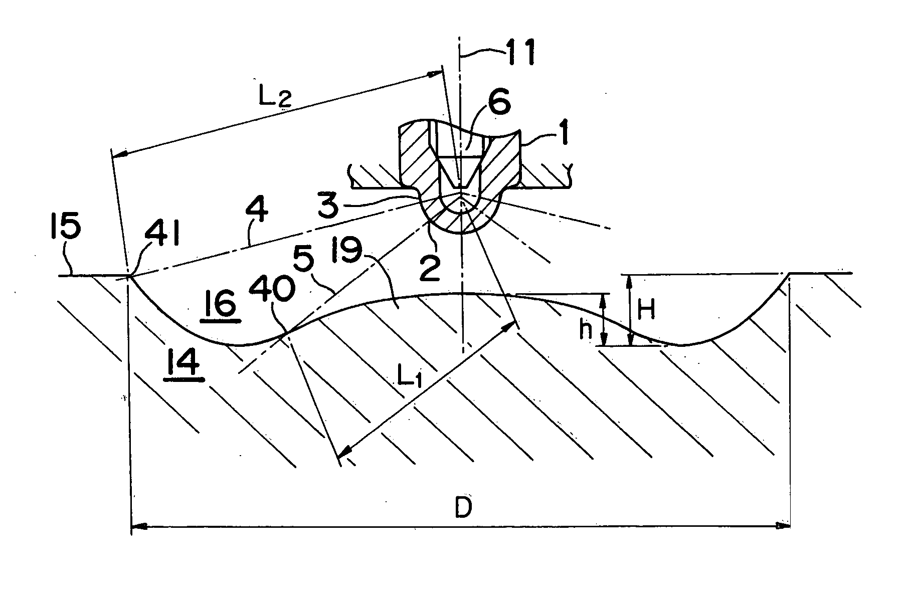
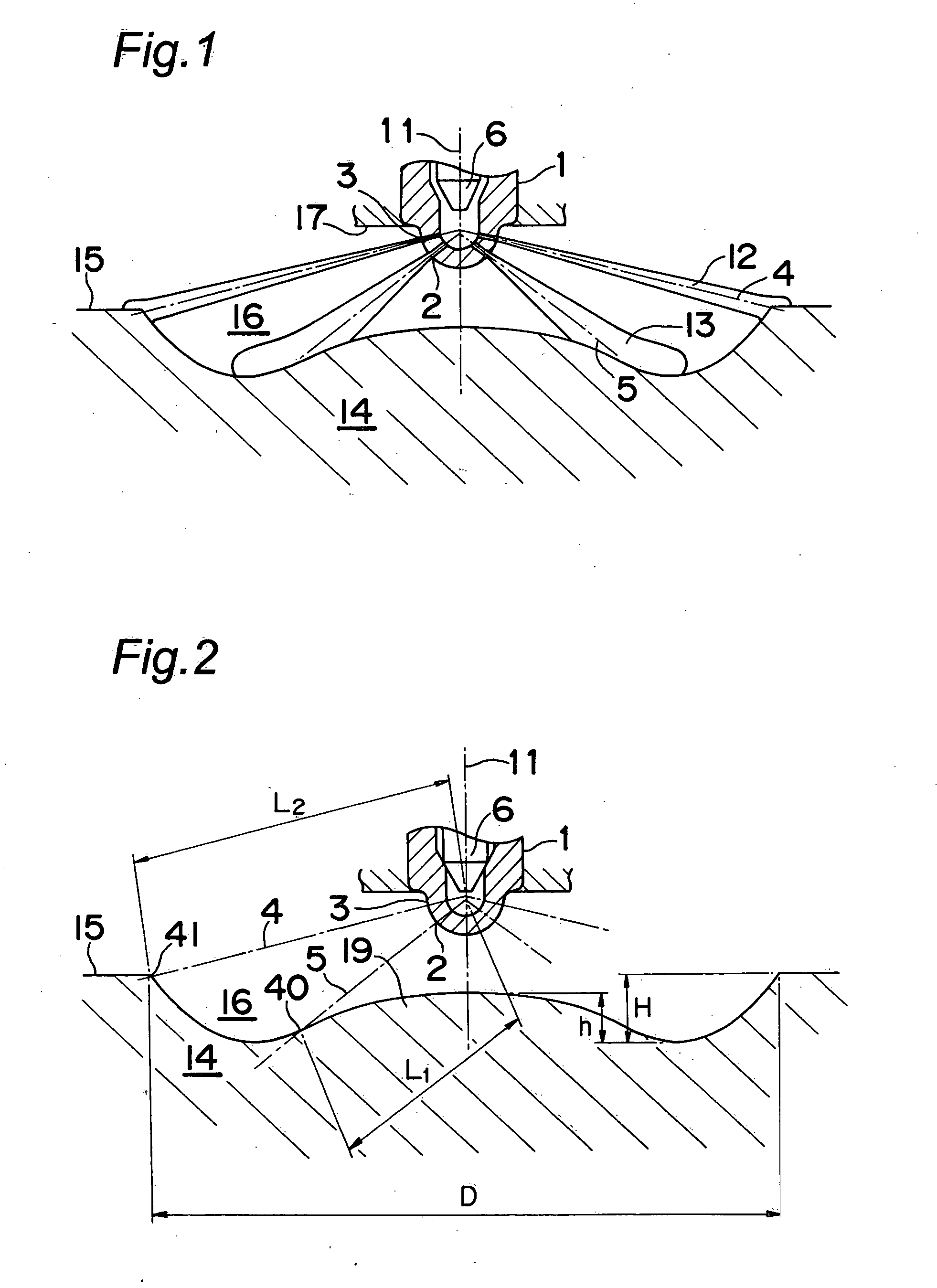
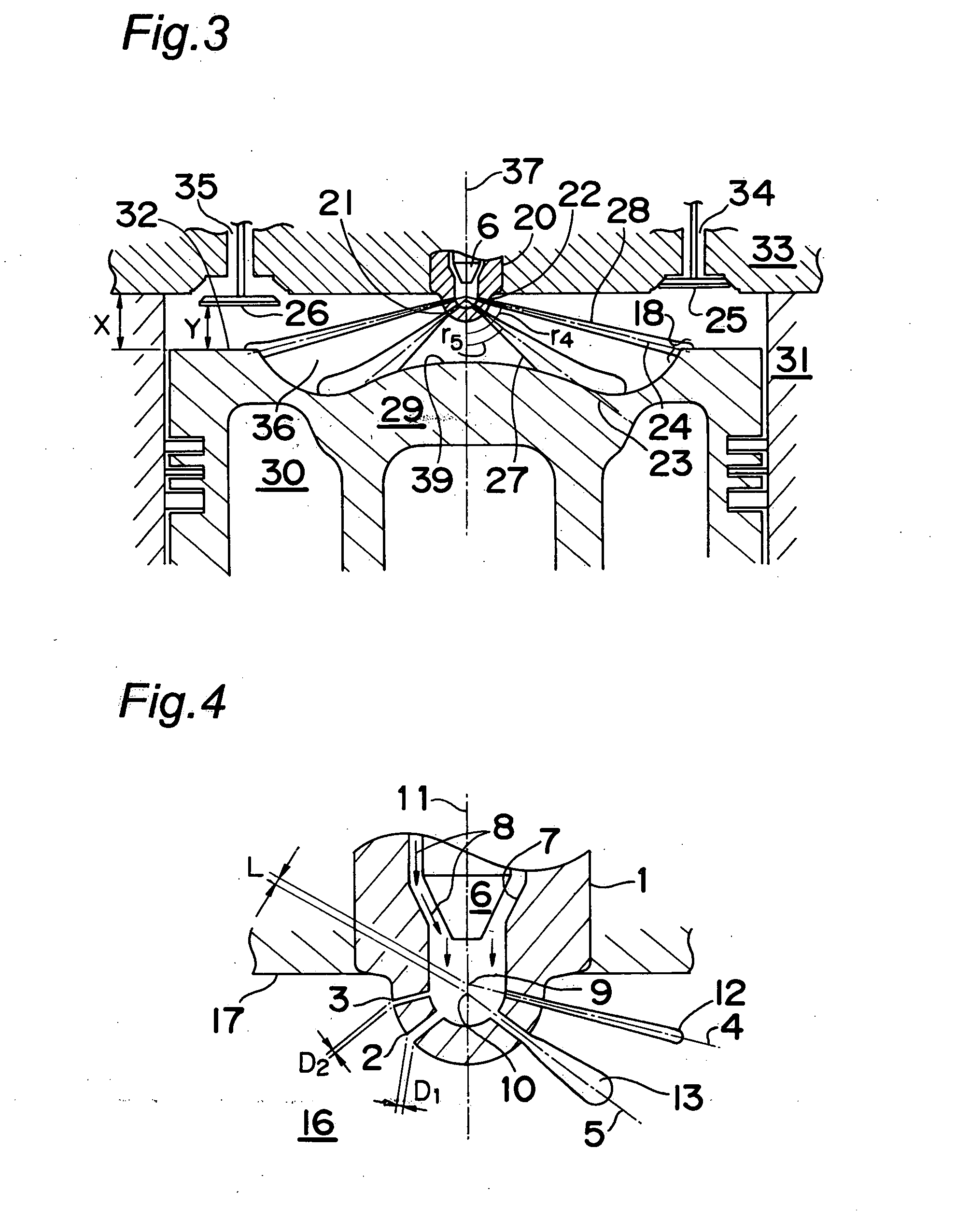
[0028]FIG. 1 is a vertically cross-sectional front view of a fuel injection valve 1 of a diesel engine into which the invention defined in claim 1 is embodied, and FIG. 4 is an enlarged view of the fuel injection valve 1. As shown in FIG. 1, the fuel injection valve 1 is mounted on a cylinder head 17, where the fuel injection valve 1 has a tip part which projects into a combustion chamber 16, in which the tip part has a plurality of lower nozzle holes 2 (i.e. first nozzle holes) and a plurality of upper nozzle holes 3 (i.e. second nozzle holes).

[0029] Inside a cavity of the fuel injection valve 1, there is provided a valve body 6. The valve body 6 can move up and down in a reciprocating manner inside the cavity thereof, by an unshown drive means such as a lift mechanism making use of its fuel pressure, an electromagnetic valve, etc. Also, as shown in FIG. 4, fuel 8 is supplied into the cavity of the fuel injection valve 1, with a pressure. When the valve body 6 moves away from a va...


PUM


Abstract

A diesel engine including a shallow-dish type combustion chamber on the top face of a piston. A fuel injection valve projects toward the combustion chamber, where a plurality of first nozzle holes are arranged in the same circumference of the fuel injection valve. A plurality of second nozzle holes having a diameter smaller than that of the first nozzle holes are provided in a circular side wall of the fuel injection valve, the circular side wall locating opposite to the tip part of the valve with respect to the first nozzle holes. The first nozzle holes and the second nozzle holes are staggered so that the sprays of the fuel ejected from the first nozzle holes and the second nozzle holes do no cross one another.

Description

TECHNICAL FIELD [0001] The present invention relates to a fuel injection valve of a diesel engine in which a shallow dish type combustion chamber is formed by a top face of a piston thereof. BACKGROUND ART [0002] In a conventional diesel engine in which a shallow dish type combustion chamber is formed by a top face of a piston thereof, a method of enlarging a diameter of a nozzle hole for injecting fuel thereinto has been generally adopted, in order to reduce the fuel consumption. If the diameter of the nozzle hole is enlarged, the atomization of the fuel spray is deteriorated and the color of the exhaust gas is worsened. [0003] As its countermeasure, it is conceivable to make the nozzle hole diameter smaller and to increase the number of the nozzle holes. With the structure, however, the distance between the nozzle holes becomes smaller, and the fuel sprays tend to cross (or overlap) one another. As a result, the amount of air to be introduced thereinto becomes short. If the pressu...

Claims


Application Information

Patent Timeline
IPC IPC(8): F02B3/06F02B23/06F02M61/14F02M61/18
CPCF02B3/06F02B23/0621F02B23/0669F02B23/0696F02B2275/14Y02T10/123F02M61/145F02M61/182F02M61/1826Y02T10/125F02M61/14Y02T10/12F02B23/06F02M61/18
Inventor TSUJIMOTO, KEIICHIHAMAOKA, SHUNJIOKADA, SHUSUKE
Owner YANMAR CO LTD
Why Eureka
Try Eureka