

Radiation tube structure
- Summary
- Abstract
- Description
- Claims
- Application Information
AI Technical Summary
Benefits of technology
Problems solved by technology
Method used
Image

Examples
Embodiment Construction
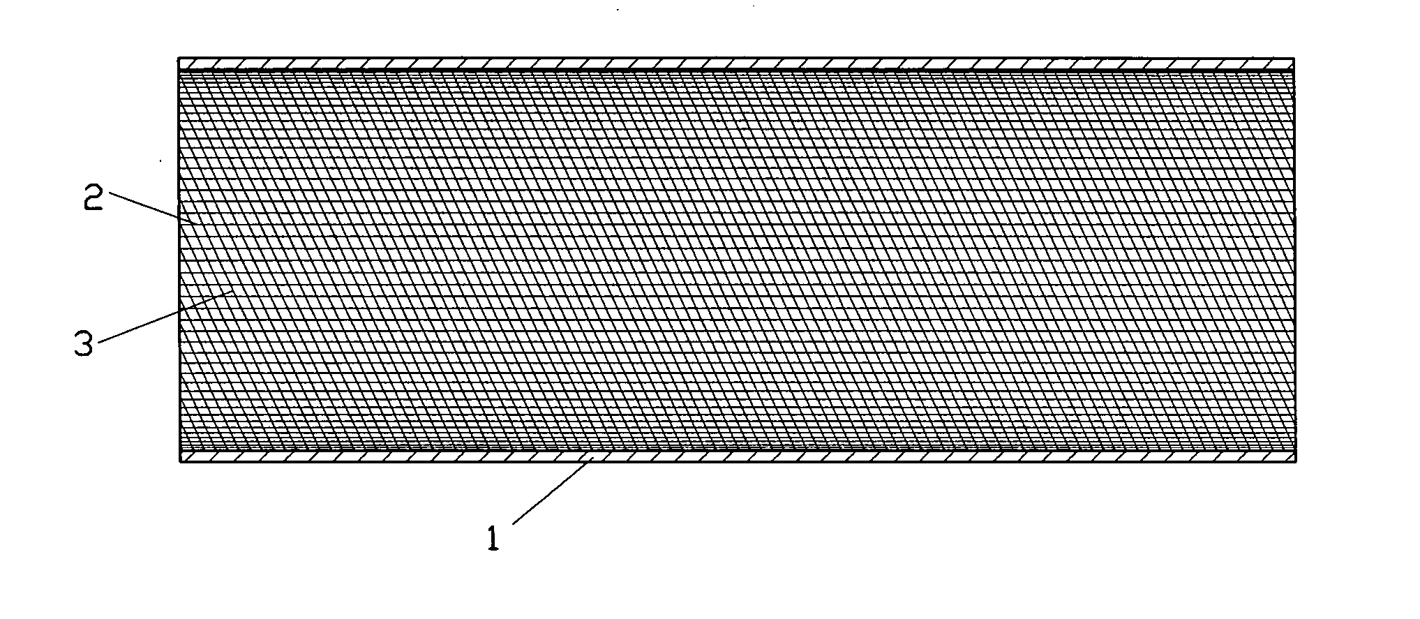
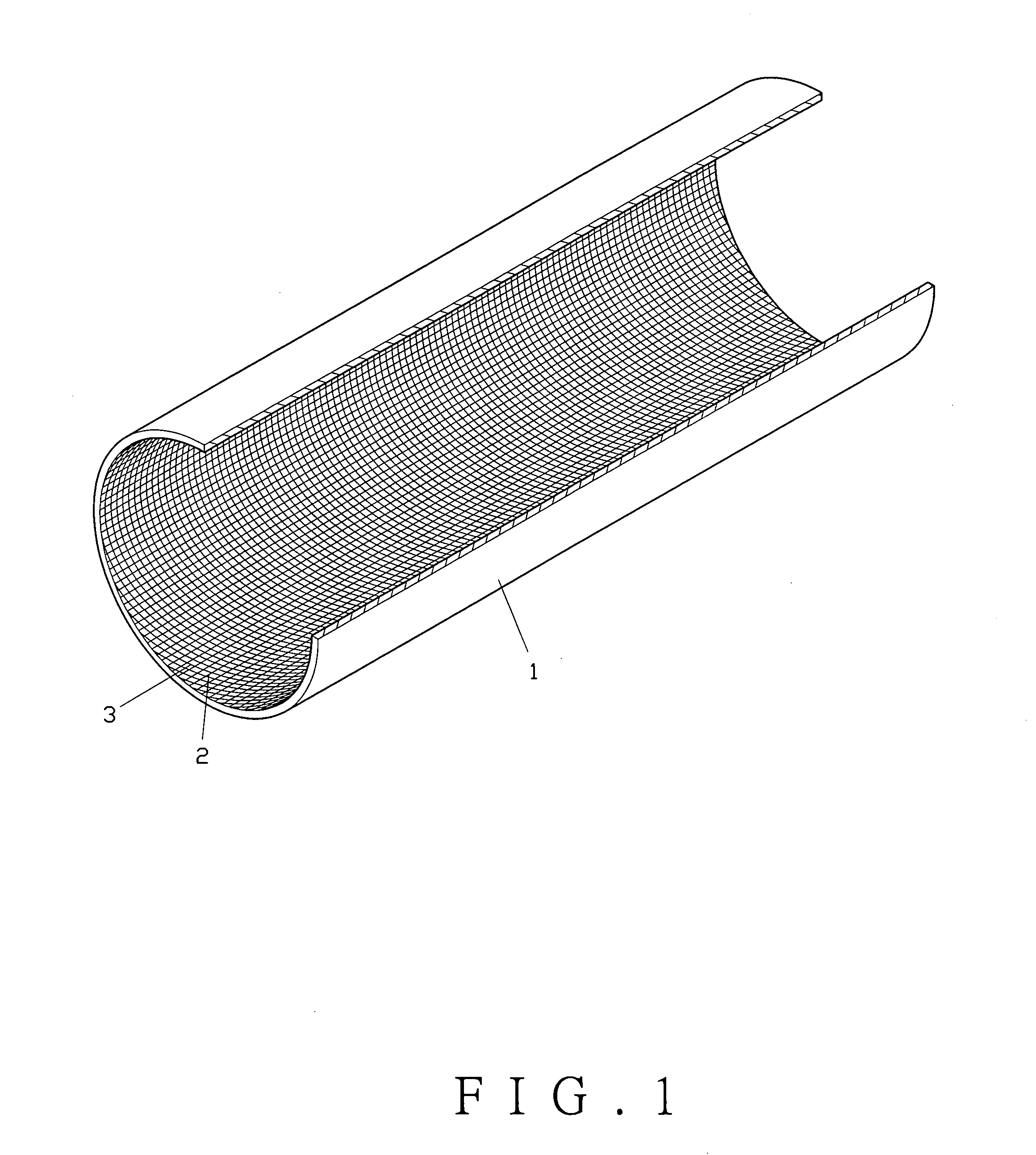
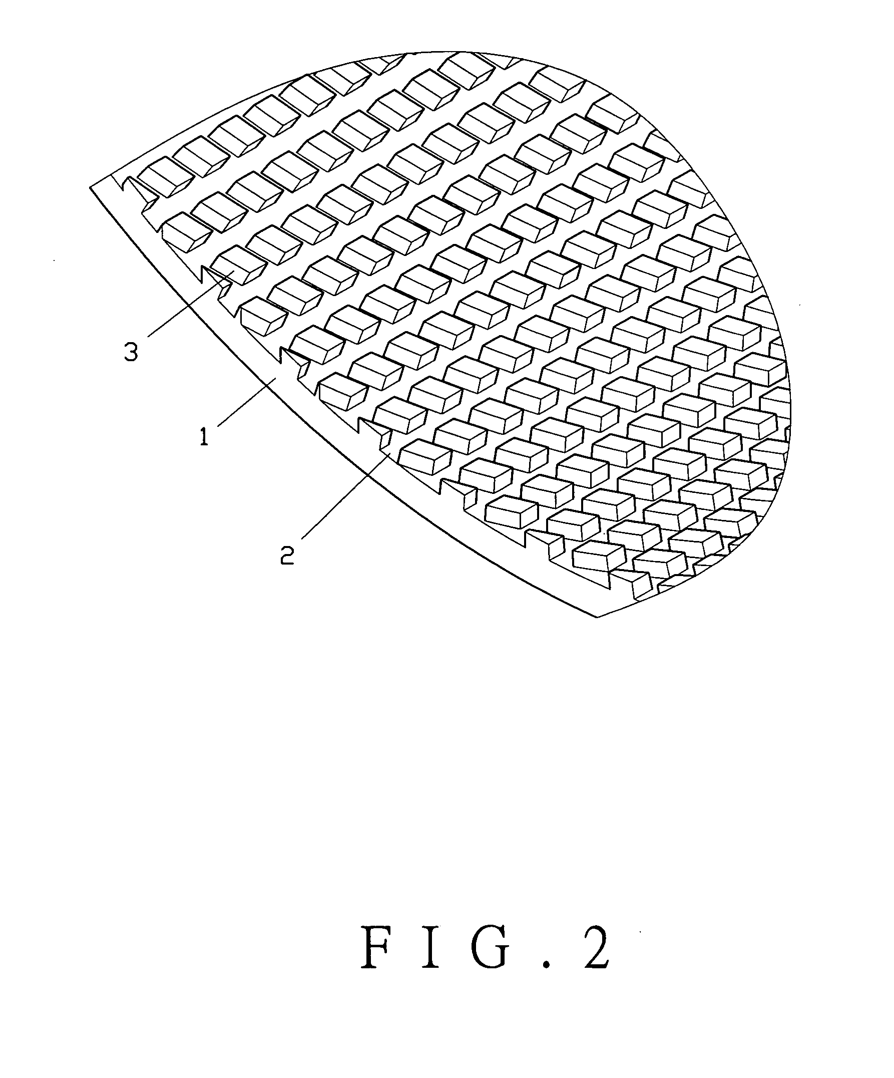
[0018] A radiation tube structure of the present invention, as shown in FIGS. 1 and 2, comprises a mental tube 1 broached with lengthwise grooves 2 and continuous circular grooves 3 on the internal wall. (The circular grooves 3 may be milled in circle formed independently or in a spiral method.) The circular grooves 3 cross the lengthwise grooves 2 to form grids on the internal wall.
[0019] To practice, as shown in FIG. 3, coolant fluid flows through the interior of the tube 1. The grids formed by the lengthwise grooves 2 and the circular grooves 3 increase the surface. Thus, the coolant fluid will be in contact with larger surface. This helps the coolant fluid to spread more evenly on the surface of the internal wall of the tube 1. The capillary effect will reach to the best effect in dissipating heat within the tube 1.
[0020]FIG. 4 shows a second embodiment of the present invention. The internal wall of a tube 4 is milled with circular grooves 5 in one direction. After this proces...
PUM
| Property | Measurement | Unit |
|---|---|---|
| Structure | aaaaa | aaaaa |
Abstract
Description
Claims
Application Information