Battery activation circuit

Inactive Publication Date: 2005-06-09
ZEST LABS INC
View PDF84 Cites 38 Cited by
  • Summary
  • Abstract
  • Description
  • Claims
  • Application Information

AI Technical Summary

Benefits of technology

[0032] The present invention includes an activate circuit and activate command structure that allows devices which are semi-passive (e.g., battery powered) to detect a particular sequence of data that instructs the device to activate. If the device does no

Problems solved by technology

However, the bar code still requires manual interrogation by a human operator to scan each tagged object individually with a scanner.
This is a line-of-sight process that has inherent limitations in speed and reliability.
In transit, these outer labels are often damaged or lost.
Error rates at each point in the supply chain have been 4-18% thus creating a billion dollar inventory visibility problem.
Early field trials have shown that the currently available passive short-range Class-1 and Class-2 tags are often inadequate for tagging pallets and many types of cases.
The problems with these passive tags are particularly severe when working with “RF-unfriendly” m

Method used


Image

  • Battery activation circuit
  • Battery activation circuit
  • Battery activation circuit

Examples


Embodiment Construction

[0062] The following description is the best embodiment presently contemplated for carrying out the present invention. This description is made for the purpose of illustrating the general principles of the present invention and is not meant to limit the inventive concepts claimed herein.

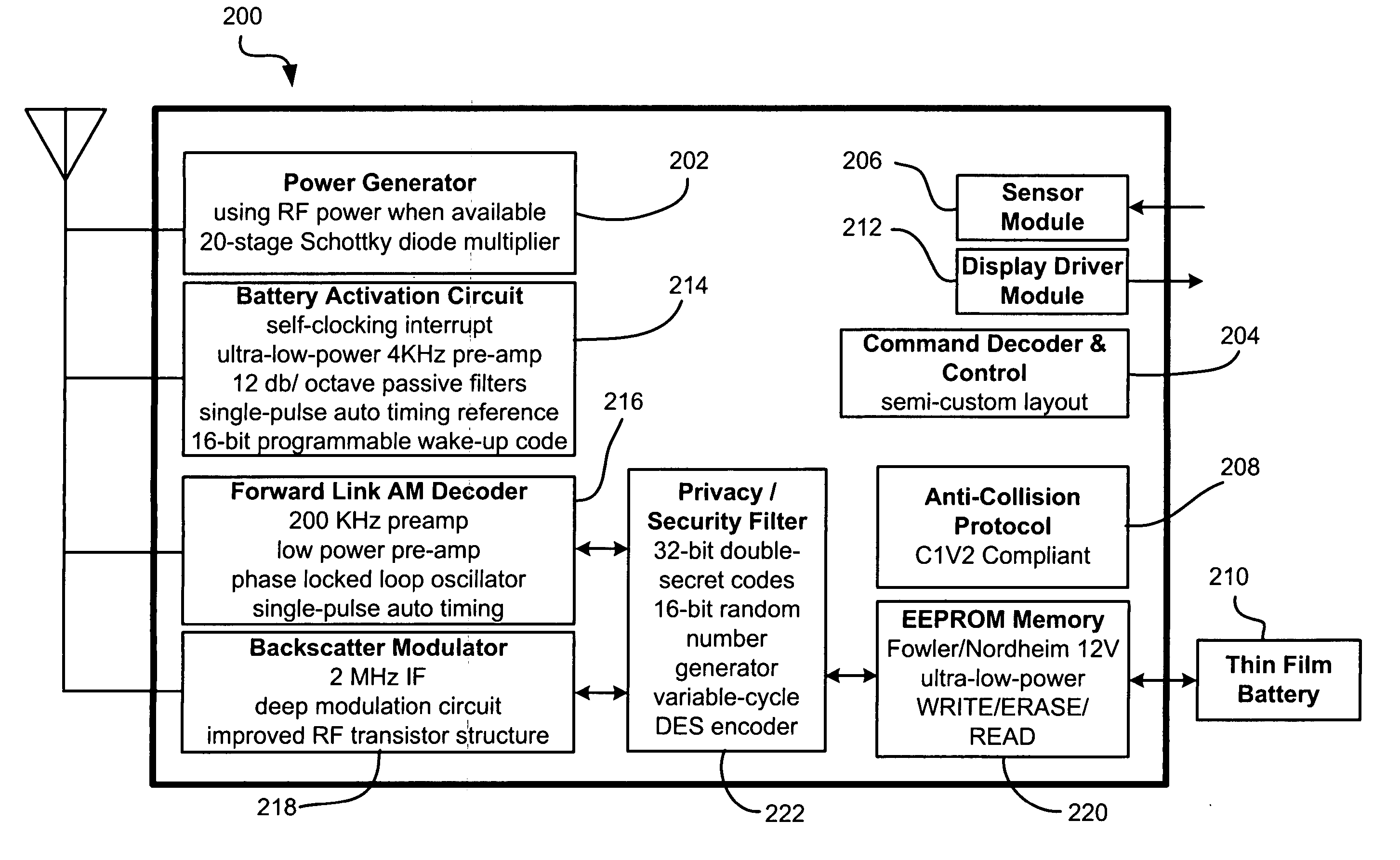
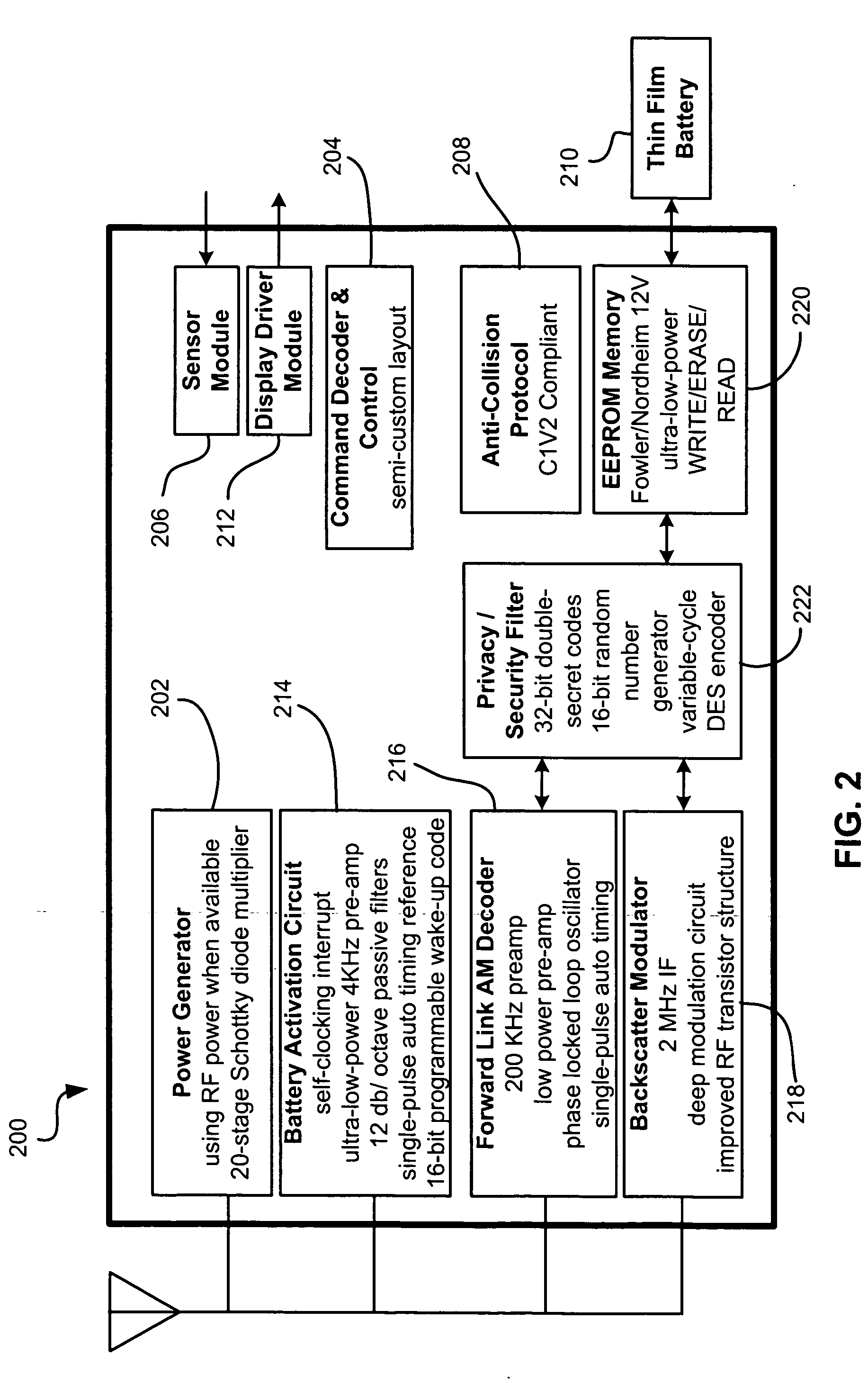
[0063] The present invention is preferably implemented in a Class-3 or higher Class chip. FIG. 2 depicts a circuit layout of a Class-3 chip 200 according to a preferred embodiment for implementation in an RFID tag. This Class-3 chip can form the core of RFID chips appropriate for many applications such as identification of pallets, cartons, containers, vehicles, or anything where a range of more than 2-3 meters is desired. As shown, the chip 200 includes several industry-standard circuits including a power generation and regulation circuit 202, a digital command decoder and control circuit 204, a sensor interface module 206, a C1V2 interface protocol circuit 208, and a power source (battery) 210. A ...


PUM


Abstract

A system and method for selectively activating a device based on an activate command. A circuit, in low power mode, listens for an activate command. The activate command includes a preamplifer centering sequence, an interrupt signal, and an activate code. The circuit receives a signal that may or may not be an activate command, self-biases the signal based on the preamplifer centering in the preamp/gain control, then determines whether the interrupt signal is of the proper length in the interrupt circuit. If the interrupt is not the proper length, the process stops. If it is the proper length, the command is recognized as an activate command, and a data slicer compares the activate code to a prestored value. If the activate code matches the prestored value, the device is powered up. If they do not match, the device is not initiated.

Description

RELATED APPLICATIONS [0001] This application claims priority from U.S. Provisional Patent Application Ser. No. 60 / 528,148, filed Dec. 9, 2003.FIELD OF THE INVENTION [0002] The present invention relates to power conserving circuitry, and more particularly, this invention relates to circuits that are selectively activatable for power conservation. BACKGROUND OF THE INVENTION [0003] Automatic identification (“Auto-ID”) technology is used to help machines identify objects and capture data automatically. One of the earliest Auto-ID technologies was the bar code, which uses an alternating series of thin and wide bands that can be digitally interpreted by an optical scanner. This technology gained widespread adoption and near-universal acceptance with the designation of the universal product code (“UPC”)—a standard governed by an industry-wide consortium called the Uniform Code Council. Formally adopted in 1973, the UPC is one of the most ubiquitous symbols present on virtually all manufac...

Claims


Application Information

Patent Timeline
IPC IPC(8): G06K19/07
CPCG06K19/0705G06K19/0723G06K19/0712G06K19/0707
Inventor STEWART, ROGER GREENPALEY, DANIEL NOAH
Owner ZEST LABS INC
Why Eureka
Try Eureka