Method and device for separating different emission wavelengths in a scanning microscope

a scanning microscope and emission wavelength technology, applied in the direction of instruments, electric discharge lamps,spectrum investigation, etc., can solve the problems of sequential scan, high cost, and multiple scanning of specimens, and achieve the effect of increasing imaging speed

Active Publication Date: 2005-06-09
LEICA MICROSYSTEMS CMS GMBH
View PDF7 Cites 34 Cited by
  • Summary
  • Abstract
  • Description
  • Claims
  • Application Information

AI Technical Summary

Benefits of technology

[0006] Thus, it is an object of the present invention to provide a method and a device to separate different emission wavelengths in a scanning microscope of the above-mentioned type in a simple manner in such a way

Problems solved by technology

A particular drawback associated with the prior-art sequential scan is that the specimen has to be scanned several times in order to generate the individual images.
This procedure is extremely time-consuming since the imaging speed is essentially limited by the speed of the scanning procedure.
Moreover, the sequential sca

Method used


Image

  • Method and device for separating different emission wavelengths in a scanning microscope
  • Method and device for separating different emission wavelengths in a scanning microscope
  • Method and device for separating different emission wavelengths in a scanning microscope

Examples


Embodiment Construction

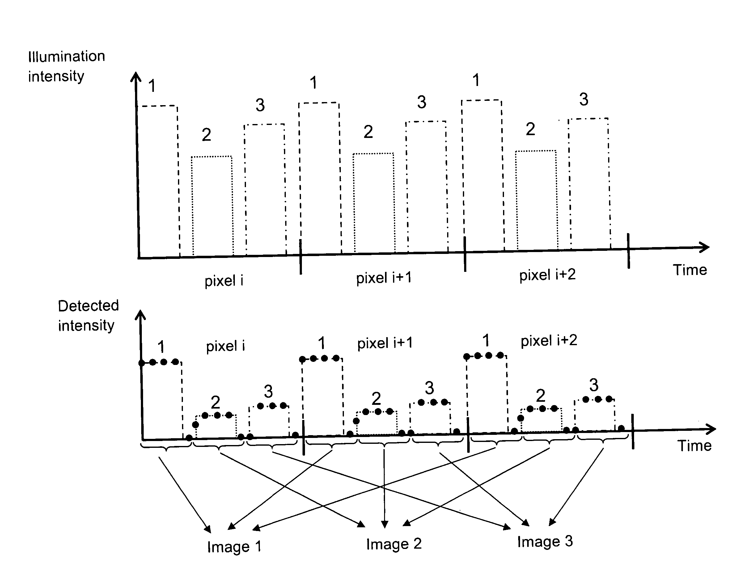
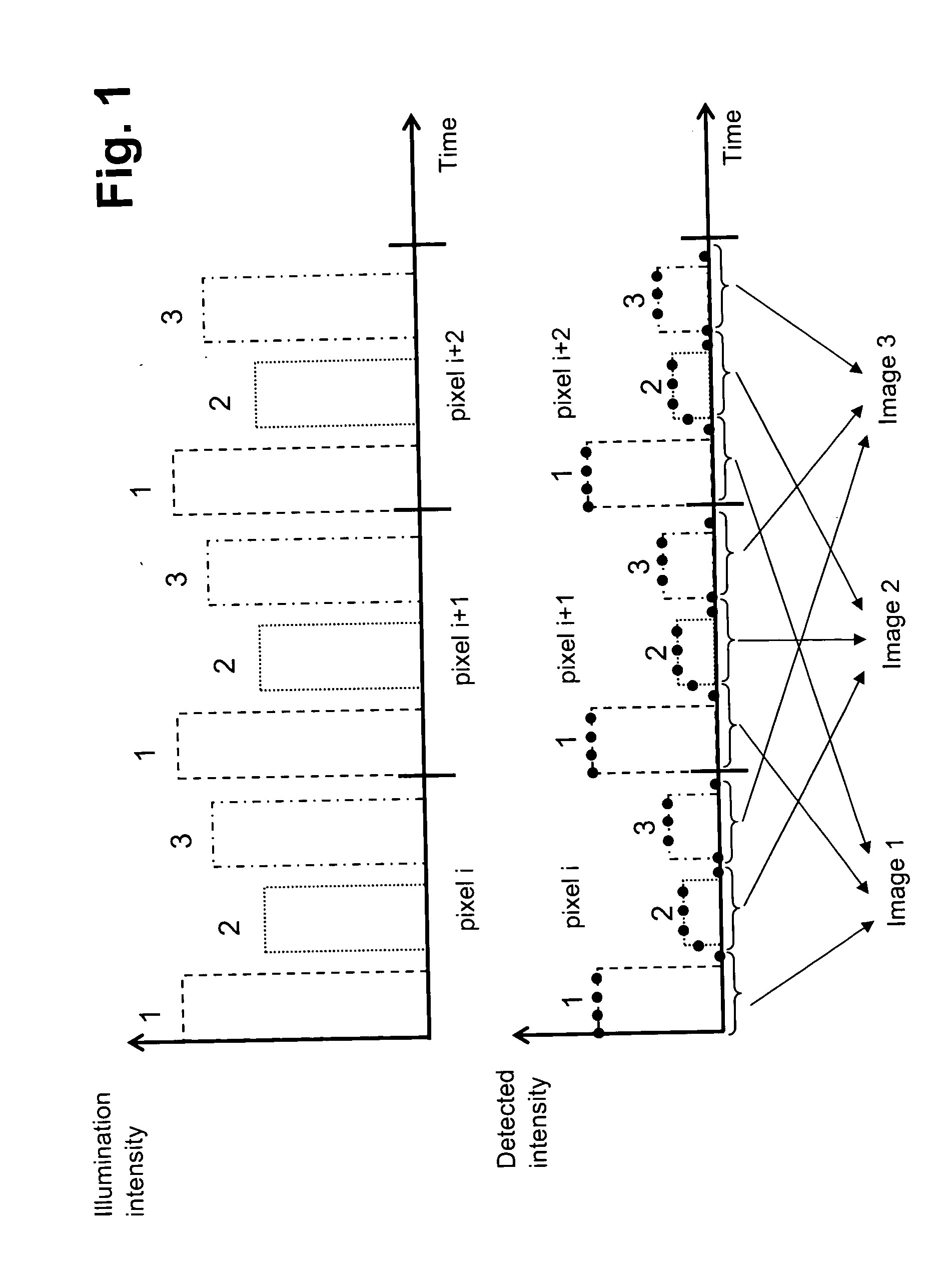
[0029] With reference being had to FIG. 4, FIG. 1 shows two diagrams whereby the illumination intensity of specimen 4 over the course of time of the scanning procedure is depicted in the upper diagram. Specimen 4 is irradiated with a total of three excitation wavelengths 1, 2, 3 according to a predefinable illumination scheme. In the embodiment depicted in FIG. 1, an illumination scheme has been chosen which shows a time sequence of applied individual excitation wavelengths 1, 2, 3 that recurs regularly over the course of time of the scanning procedure. Here, the recurring sequence has been selected in such a way that a complete cycle of the sequence corresponds to one pixel of the later image.

[0030] The lower diagram shows the detected intensity of the emission wavelengths that correspond to the excitation wavelengths 1, 2, 3 over the course of time of the scanning procedure. The detector 5 is read out separately for each applied excitation wavelength 1, 2, 3. The reading-out of t...


PUM


Abstract

A method for separating different emission wavelengths in a scanning microscope includes scanning a specimen with an illuminating light beam by passing the illuminating light beam over the specimen using a beam deflector, and selectively applying each of a plurality of excitation wavelengths to the illuminating light beam during the scanning according to a predefinable illumination scheme. Emission light coming from the specimen is detected using a detector, the emission light including emission wavelengths corresponding to the excitation wavelengths. The detector is read out when an excitation wavelength is applied so as to provide detected signals. The detected signals are associated with the respective excitation wavelengths using the illumination scheme.

Description

[0001] Priority is claimed to German patent application 103 57 584.7, which is hereby incorporated by reference herein. [0002] The present invention relates generally to a method and to a device to separate different emission wavelengths in a scanning microscope. In particular, the present invention relates to a method and to a device in which a specimen is scanned with an illuminating light beam that is passed over the specimen by means of a beam deflector, the illuminating light beam having different, selectively applied excitation wavelengths, and the emission light coming from the specimen and containing the emission wavelengths that correspond to the excitation wavelengths is picked up in at least one detector. BACKGROUND [0003] Methods and devices of the kind under discussion here have long been known in actual practice and they are used especially in fluorescence microscopy. In the realm of fluorescence microscopy, a specimen to be examined is often dyed with several fluoresc...

Claims


Application Information

Patent Timeline
IPC IPC(8): G01J3/44G02B21/00G02B21/16G02B21/06
CPCG02B21/16G01J3/4406
Inventor SEYFRIED, VOLKERSTORZ, RAFAEL
Owner LEICA MICROSYSTEMS CMS GMBH
Why Eureka
Try Eureka