Radar systems

Inactive Publication Date: 2005-06-09
SMITHS GRP PLC
View PDF8 Cites 10 Cited by
  • Summary
  • Abstract
  • Description
  • Claims
  • Application Information

AI Technical Summary

Benefits of technology

[0013] Two conventional marine vessel radar systems and a novel system according to the prese...

Problems solved by technology

Both these systems have disadvantages in that they require special form...

Method used


Image

  • Radar systems
  • Radar systems
  • Radar systems

Examples


Embodiment Construction

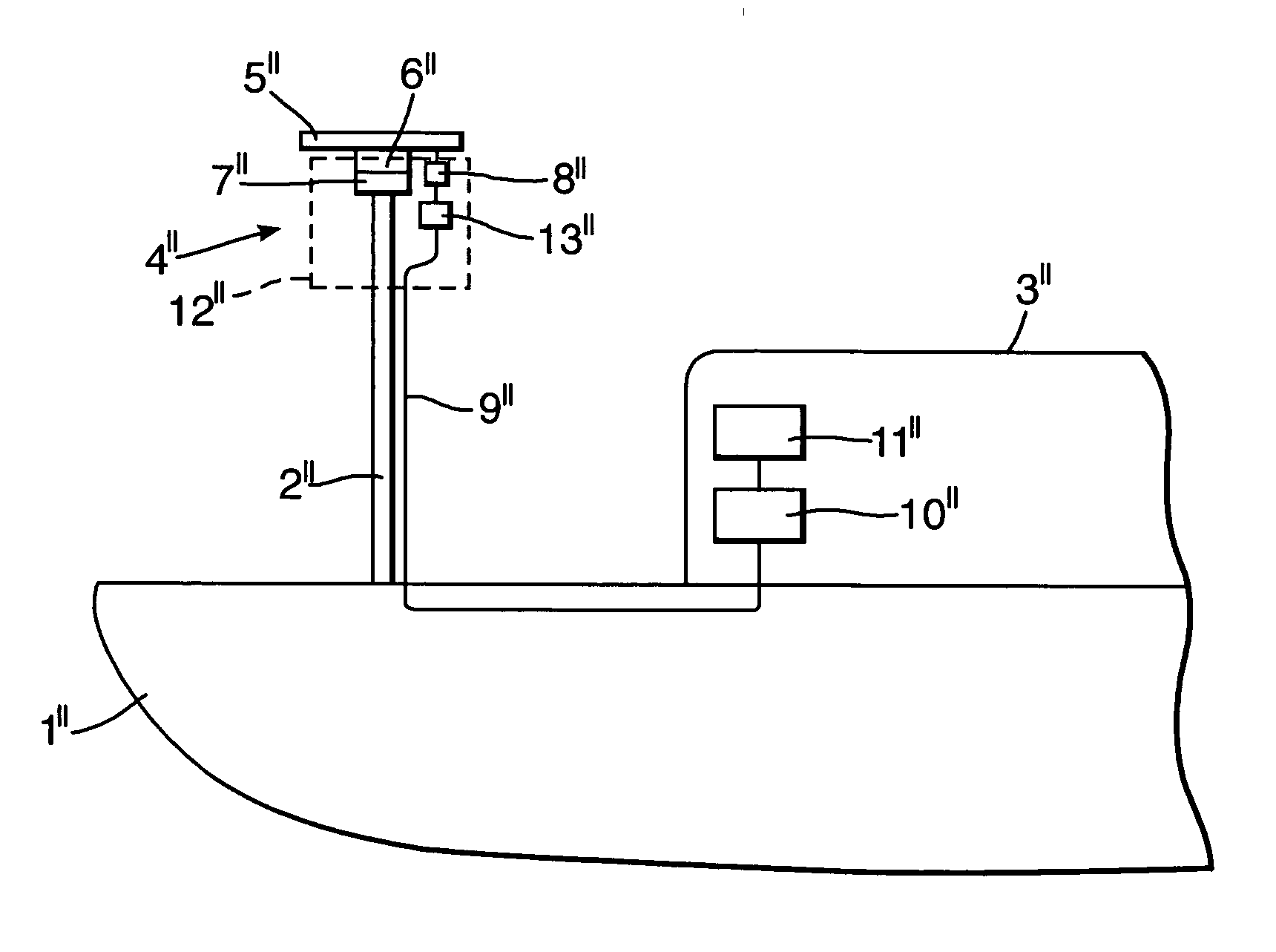
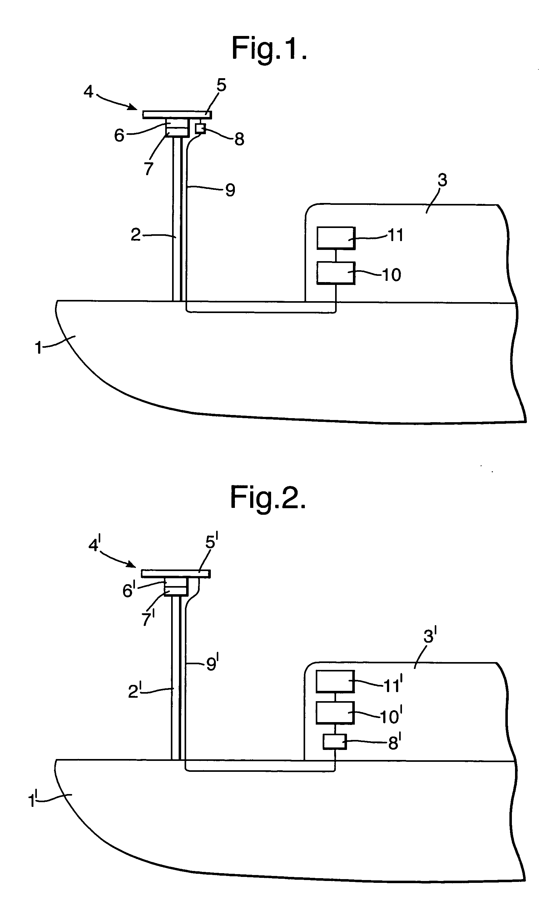
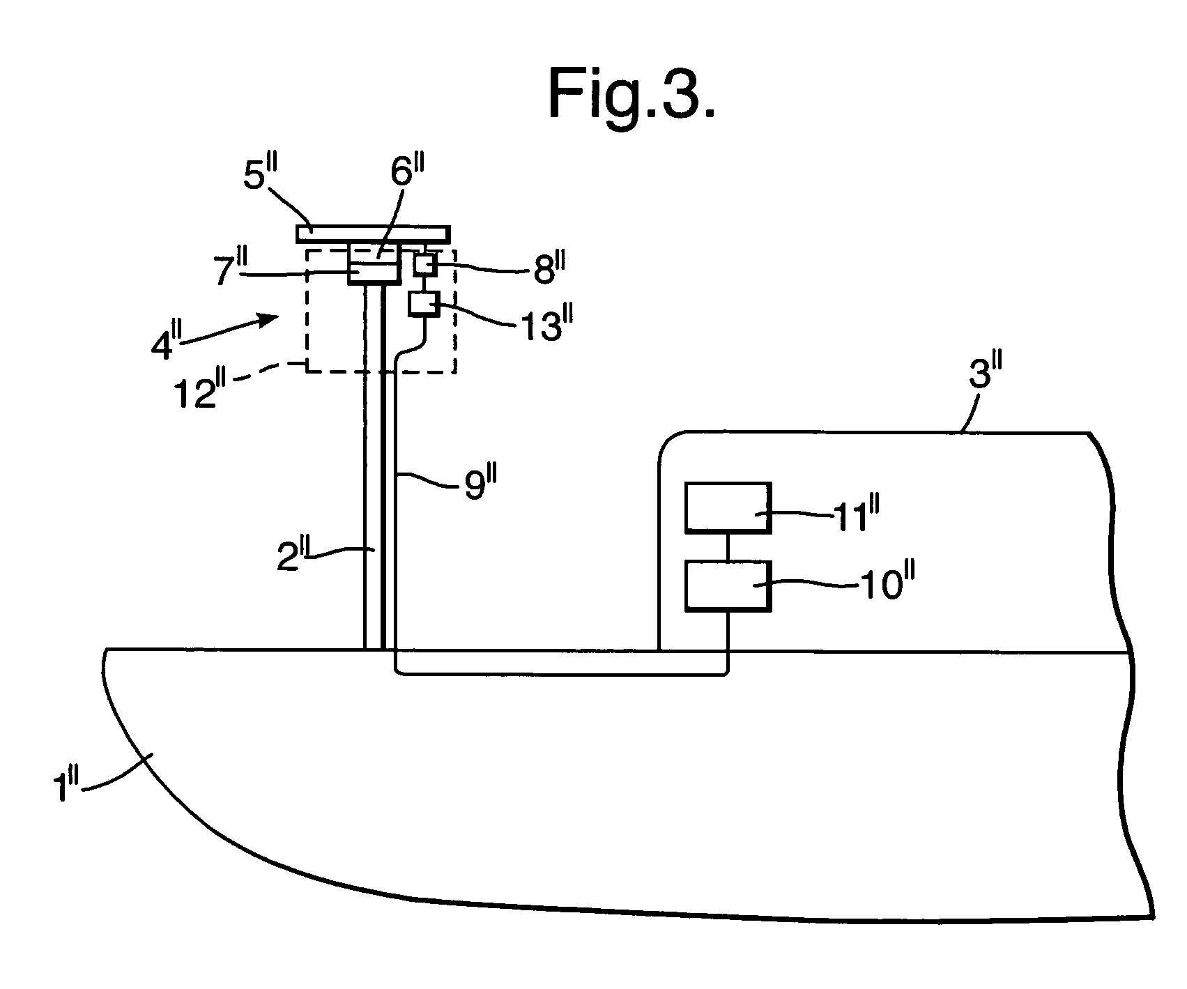
[0017] With reference first to FIG. 1 there is shown a marine vessel 1 with a mast 2 and an enclosed structure such as a bridge 3. An antenna unit 4 is secured at the top of the mast 2, the unit comprising an antenna 5 coupled with a gearbox 6, which is driven by an electrical motor 7. The unit 4 also includes a transceiver 8 coupled with the antenna 5 for supply of microwave energy to and from the antenna. The transceiver 8, therefore, is also mounted towards the top of the mast 2. The transceiver 8 produces an analogue electrical output and is connected to one end of cabling 9, which includes dedicated lines for control of the motor and separate lines for video, sync and heading line information. The cabling 9 extends down the mast 2 and through the vessel 1 to the structure 3 where it connects with a processing unit 10. The processing unit 10 provides an output to a display 11 or other utilisation means such as a store, voyage data recorder or the like. Because the analogue signa...


PUM


Abstract

A radar system for a marine vessel has an antenna unit mounted at the top of a mast and a radar display at a remote location. The antenna unit comprises an outer housing containing: an antenna, a motor and gearbox to rotate the antenna to scan in azimuth, a transceiver connected to receive radar signals from the antenna and an analogue-to-digital converter. Digital signals from the converter are supplied down the mast via cabling, which extends to a processor adjacent the display. The processor converts the digital signals into a form for display.

Description

BACKGROUND OF THE INVENTION [0001] This invention relates to radar systems. [0002] International regulations now require vessels greater than 300 gross tonnage to be fitted with marine navigation radar. Often much smaller vessels also carry navigation radar. [0003] Marine radar systems comprise an antenna mounted at the top of a mast with a motor and gearbox to rotate the antenna about a vertical axis, to scan in azimuth. A transceiver provides the microwave signal propagated by the antenna and also is supplied with signals received by the antenna. The transceiver converts the received signals into analogue electrical signals, which are then supplied to a processor for digitisation and display. [0004] In a so-called “upmast” system, the transceiver is mounted directly under the antenna at the top of the mast. The transceiver supplies analogue radar information signals via a cable down the mast to a remote processor unit, which converts the signals to a digital form for display. Sepa...

Claims


Application Information

Patent Timeline
IPC IPC(8): G01S13/937G01S7/00G01S7/03G01S13/02
CPCG01S13/9307G01S7/03G01S13/937
Inventor TAYLOR, MARTIN STUART
Owner SMITHS GRP PLC
Why Eureka
Try Eureka