Liquid crystal display device for displaying video data

a liquid crystal display and video data technology, applied in the direction of television systems, instruments, color signal processing circuits, etc., can solve the problems of increasing the cost and not describing the means of obtaining a satisfactory display, and achieve the effect of increasing the amount of back light and reducing the amount of ligh

Inactive Publication Date: 2005-06-09
PANASONIC LIQUID CRYSTAL DISPLAY CO LTD +1
View PDF2 Cites 69 Cited by
  • Summary
  • Abstract
  • Description
  • Claims
  • Application Information

AI Technical Summary

Benefits of technology

[0010] This invention intends to provide an appropriate contrast in accordance with video data and provide a liquid crystal display device that is capable of clearly displaying video images.
[0012] Further, this invention intends to provide a liquid crystal display device which is capable of improving the efficiency of utilizing the light of a back light, or is capable of reducing the electric power consumption for lighting up the back light, by obtaining an appropriate amount of light from the back light in accordance with the video data.
[0020] Preferably, when luminance in one or plural frames is lower compared with the luminance in another one or plural frames, the amount of light of a back light is decreased relatively.
[0021] Preferably, when luminance in one or plural frames is higher compared with the luminance in another one or plural frames, the amount of light of the back light is increased relatively.

Problems solved by technology

Further, although the technology described above involves a color conversion method for video data based on the setting of a lookup table and an operation method for the lattice points based on a set value, it does not describe means for obtaining a satisfactory display, for example, by combining back light control.
Further, video image scenes actually change sequentially and currently with time for video signals, but provision of a number of γ-correction memories optimal to each of the video image scenes requires a great amount of memory capacity resulting in an increase of the cost, and so it is not practical.

Method used


Image

  • Liquid crystal display device for displaying video data
  • Liquid crystal display device for displaying video data
  • Liquid crystal display device for displaying video data

Examples


first embodiment

[0056] this invention will be explained with reference to the drawings.

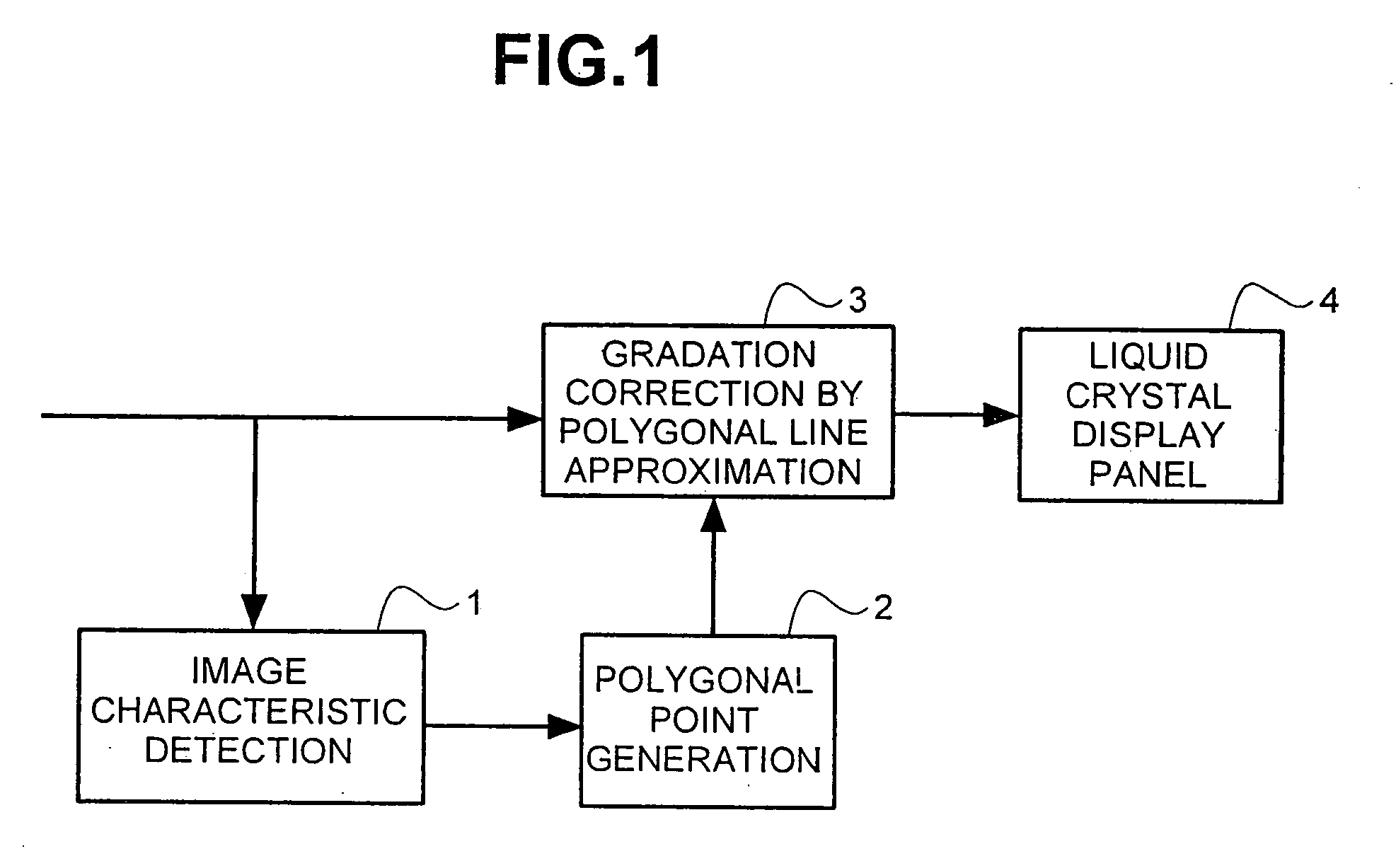
[0057]FIG. 1 is a block diagram illustrating a first embodiment of a display system using the technique according to this invention.

[0058] In FIG. 1, there are a video image characteristic detection section 1 for measuring the luminance characteristic of video signals, such as luminance distribution, maximum luminance, minimum luminance and average luminance of RGB video signals; a polygonal point generation section 2 for calculating a correction control point for gradation correction from the luminance characteristic of the video signals detected by the input video image characteristic detection section 1; a polygonal line approximation gradation correction section 3 for correcting the luminance characteristic of RGB video signals by the gradation correction control point generated by the polygonal point generation section 2; and a liquid crystal display panel 4 for displaying RGB video signals corrected with t...

second embodiment

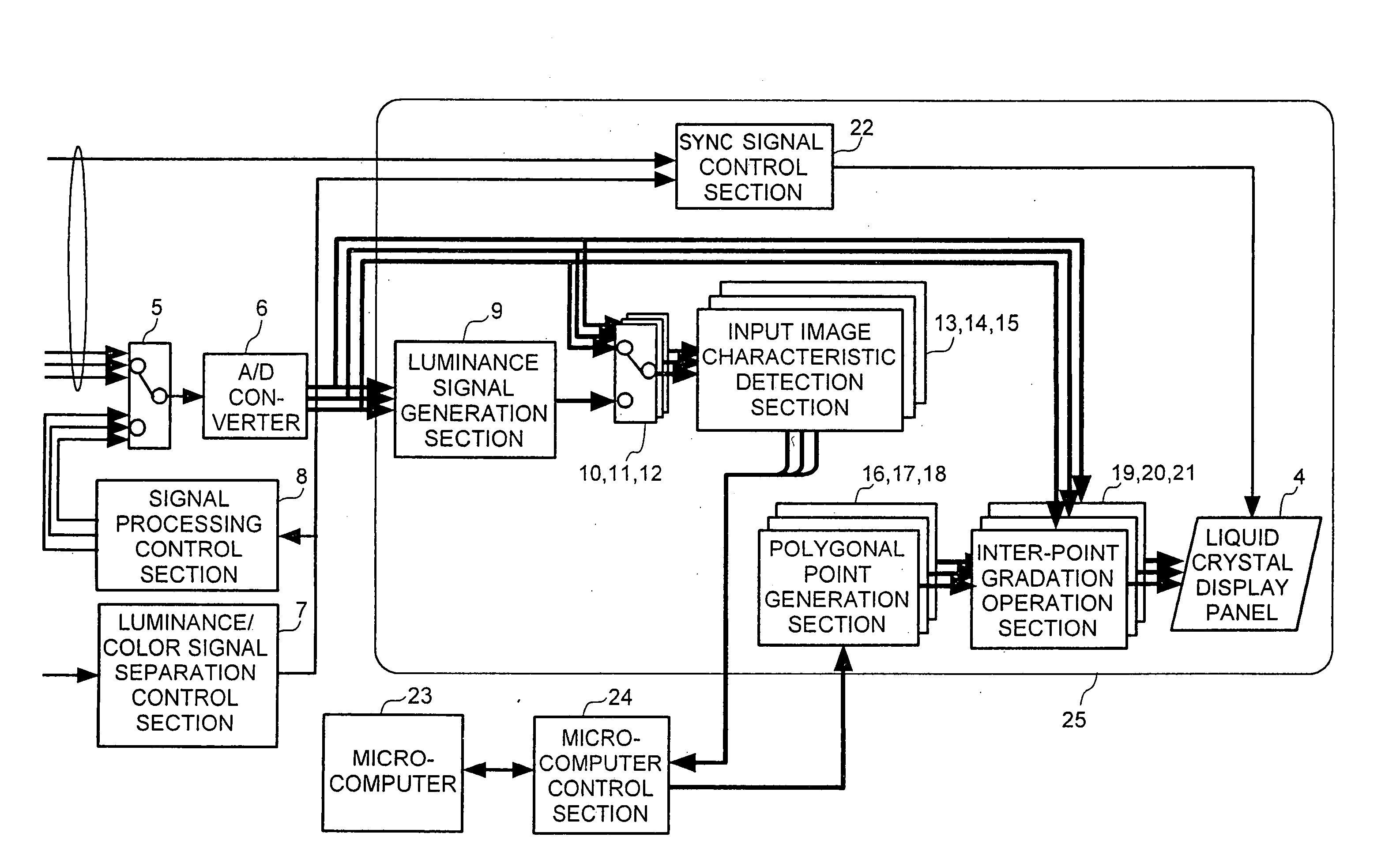
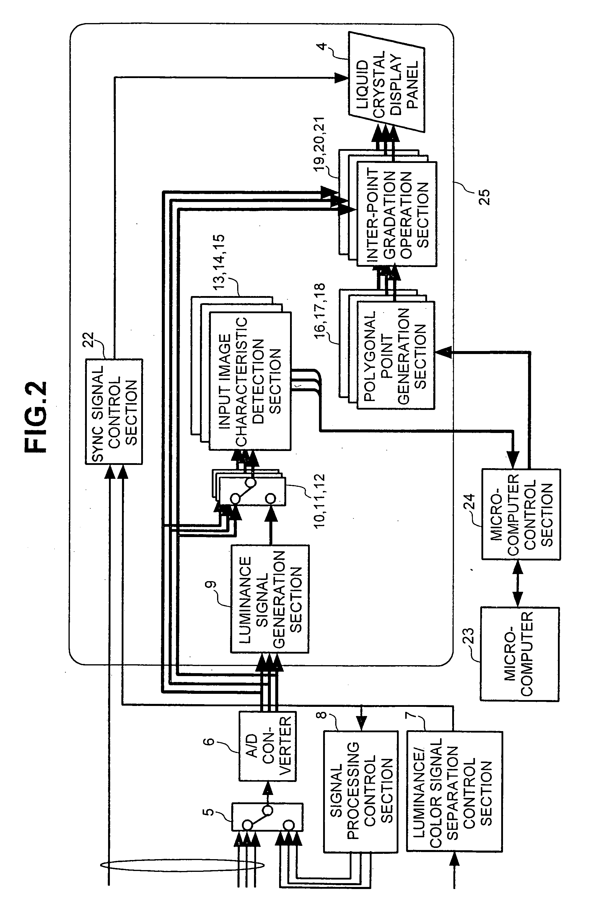
[0100]FIG. 15 is a block diagram illustrating a second embodiment using the technique according to this invention.

[0101] This embodiment additionally comprises a back light control section 65 for controlling the amount of a light produced by a back light, in addition to the already-describe features of the first embodiment. Since other portions are identical with those described for the first embodiment, a further detailed explanation thereof will be omitted.

[0102]FIG. 16 illustrates the concept used for control of the amount of light produced by the back light. The amount of light produced by the back light is controlled by the result of detection of the average luminance by the input video image characteristic detection sections 13-15. The average luminance is obtained by calculating the luminance value Y from the inputted video data and determining the average for the luminance value Y for one frame. In the second embodiment, the amount of light produced by the back light is inc...

sixth embodiment

[0153] this invention will be explained with reference to FIG. 31. The sixth embodiment is an example of a circuit for conducting gradation correction after storing the color video signal once in a frame memory and delaying the same by 1 frame.

[0154]FIG. 31 is a block diagram of a liquid crystal display device to which the sixth embodiment according to this invention is applied, in which there are a frame memory 150 for delaying the color video signal 71 by one frame period and a color video signal 151 delayed by one frame. Since other portions are identical with those already explained for the third and fourth embodiments, duplicate explanations are to be omitted.

[0155] The operation of the sixth embodiment will be explained. In FIG. 31, inputted color video signal 71 is inputted to each of a histogram detection circuit 72 and a frame memory 150. The histogram detection circuit 72 detects the histogram showing the frequency of the brightness of the color video signal 71, thereby t...


PUM


Abstract

A liquid crystal display device for displaying video data having a detection circuit for detecting a luminance distribution based on video data which is inputted, the luminance distribution being indicative of generation frequency of gradations in each of divided region which includes a plurality of gradations. The display device includes a determination circuit for determining at least one of a plurality of divided regions of higher generation frequency of gradation than that of other divided regions based on the luminance distribution, a correction circuit for correcting the video data so as to make a luminance characteristic of the at least one of the plurality of divided regions of higher generation frequency of gradation more abrupt than a luminance characteristic of the other divided regions, and a liquid crystal display panel for displaying the corrected video data. A width of the divided region is changeable.

Description

CROSS REFERENCE TO RELATED APPLICATION [0001] This is a continuation of U.S. application Ser. No. 09 / 816,077, filed Mar. 26, 2001, the subject matter of which is incorporated by reference herein.BACKGROUND OF THE INVENTION [0002] This invention concerns a display device for displaying video data (including image data and text data); and, more particularly, the invention relates, for example, to a liquid crystal display device, CRT (Cathode Ray Tube) display device, plasma display device or EL (Electroluminescence) display device. [0003] Existent color conversion methods for converting video data received from video signal generation devices, and the conversion devices therefor, have been adapted, as disclosed, for example, in J-P-A No. 11-275375, to set correction values to lattice point data for strengthening positions in a possible range of color values after conversion to a poly-dimension lookup table so as to allow values out of the possible range for the color values after conv...

Claims


Application Information

Patent Timeline
Patent Type & Authority Applications(United States)
IPC IPC(8): G09G3/20G09G3/34G09G3/36H04N5/66H04N9/69
CPCG09G3/2007G09G3/3406G09G3/3611G09G2320/0276G09G2320/0606H04N9/69G09G2320/0633G09G2320/0646G09G2320/066G09G2360/16H04N5/66G09G2320/0626G09G3/36
Inventor NISHITANI, SHIGEYUKIMAEDA, TAKESHIKAWABE, KAZUYOSHIKURIHARA, HIROSHITAKAGI, TETSUOOHASHI, TOSHIAKI
Owner PANASONIC LIQUID CRYSTAL DISPLAY CO LTD
Why Eureka
Try Eureka