Color filters and sequencers using color-selective light modulators

a color filter and color-selective light technology, applied in the field of color selective polarization modulation, can solve the problems of not being able to individually solve the viewer, neither efficient light use, and more hardware intensive techniques, and achieve the effect of high spectral contras

Inactive Publication Date: 2005-06-09
REAID INC
View PDF90 Cites 15 Cited by
  • Summary
  • Abstract
  • Description
  • Claims
  • Application Information

AI Technical Summary

Benefits of technology

[0020] The present invention provides color selective light modulation, and color filters and sequencers utilizing the same. Color separation is accomplished with nearly lossless retarder films, providing high spectral contrast between transmission and extinction, with arbitrarily steep transition slopes.
[0022] In a preferred embodiment, each filter stage controls the transmission of an additive primary color locally in an analog fashion, thus integrating image and color generation. One preferred embodiment eliminates internal polarizers between filter stages, thereby providing a full-color display with only an input polarizing means and an output polarizing means. A preferred two-polarizer configuration operates in an additive mode, which exhibits benefits over subtractive mode schemes.
[0026] In a preferred embodiment, the polarization analyzer comprises a second retarder stack positioned between the modulator and an analyzing polarizer. Such structures have the potential of providing complete transmission, or complete blocking, of an unmodulated spectrum, while permitting 100% luminance modulation of the complementary spectrum. The relationships between retarder stacks (i.e. number, orientation and retardation of each retarder film) significantly influences the overall behavior. Exemplary retarder stack relationships represent cooperative polarization transformations, yielding full luminance modulation of a well-defined spectral band, with zero modulation of the complementary spectral band.
[0029] Unlike common paths displays and color sequences of the prior art, a two-polarizer CSLM permits operation in an additive mode rather than a subtractive mode, by eliminating the need to analyze the state of polarization after each stage. This eliminates the interaction of filter stages on a power basis. Inverting the spectra, such that additive primaries become subtractive primaries, white becomes black, and vice-versa, yields important performance improvements. Specifically, the filter stages become independent in generating additive primaries, while a high density black state can be achieved. This is accomplished with little impact on the subtractive primaries and the white state.
[0030] The CSLM of the present invention contains the active polarization modulating element within the retarder stack, rather than adjacent to the retarder stack, thus providing modulation between a filtered spectrum and a neutral spectrum. It is an object of this invention to provide high throughput color filters with outputs arbitrarily selectable from the set of R, G, B, C, M, Y, W, and K (black). It is a further object of this invention to produce multi-stage color filters and sequencers that contain no internal analyzing polarizers. It is yet a further object of this invention to produce color filters with fixed color coordinates which do not reply upon accurate active polarization modulating element characteristics. It is also an object of this invention to integrate such filters with displays and digital cameras to yield high performance color generation, with or without neutral outputs.

Problems solved by technology

This technique requires that the sub-pixels be sufficiently small that they are not individually resolvable by the viewer.
However, neither makes efficient use of light, because displaying an additive primary color generally means blocking the complementary subtractive primary.
Though this technique is more hardware intensive, it is in principle three times brighter than either spatial or temporal color techniques.
Compared to additive split-path displays, subtractive displays have unique design challenges.
In direct view display systems, there are additional complications associated with color quality and parallax the when the display is viewed off-normal.
Performance of related art subtractive displays has been hampered by a number of factors.
For instance, color quality and throughput are poor due to the shallow transition slope and low peak transmission of many dye polarizers.
More fundamentally, the optical density of the black state is typically poor when using three subtractive filter stages.
When the blocked additive primaries are adjacent primaries, there is typically an unwanted leakage.
This represents a difficult spectral management problem, because contrast ratios can plummet with even small side lobe amplitudes.
Furthermore, designs that achieve acceptable contrast are frequently not robust against small fabrication tolerances, variations in modulator uniformity, and environmental changes.
However, this cannot be done without adversely affecting the color coordinates of the primary colors.
While passive notch filtering can be provided to eliminate interprimary light, there is an associated insertion loss and an increase in cost.
As in printing systems, a fourth “black-panel” can be inserted to improve contrast ratio, which again increases cost and complexity and reduces throughput.
PIFs have traditionally been used for spectrometry instrumentation, because they are bulky, complex to fabricate, and require calibration.
Such spectral profiles are not considered ideal for display, particularly in the blue, where adequate red blocking determines an unnecessarily narrow bandpass width.
Another issue with complementary color switch technology concerns the robustness of the output.
In the driven state, the cell can be made to vanish at normal incidence, giving color polarizer limited performance.
However, a significant retardence is typically experienced when viewing the filter off-normal, which can significantly influence the color coordinate.
Thus, achieving a stable color coordinate using complementary switching can place impractical tolerances and, in some cases, demand unattainable performance on the cell.

Method used


Image

  • Color filters and sequencers using color-selective light modulators
  • Color filters and sequencers using color-selective light modulators
  • Color filters and sequencers using color-selective light modulators

Examples


embodiment 2

SA Crossed Stack, 0°-Oriented ZTN LC Modulator, Parallel Polarizer

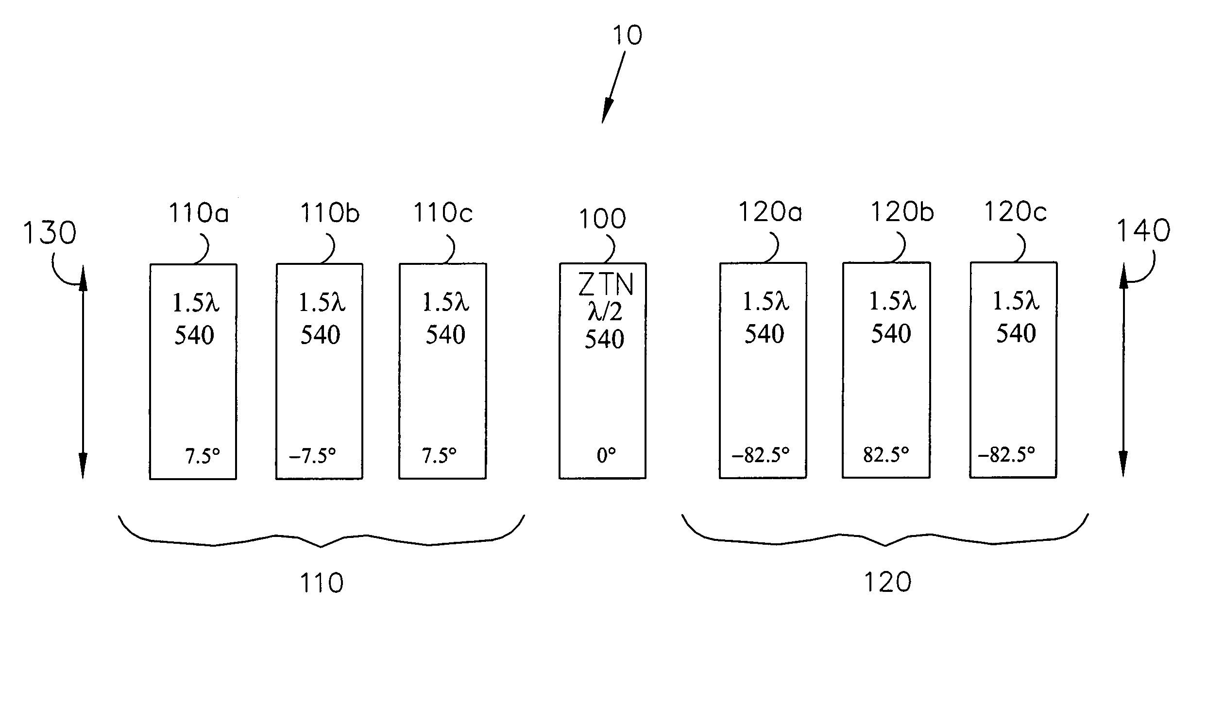
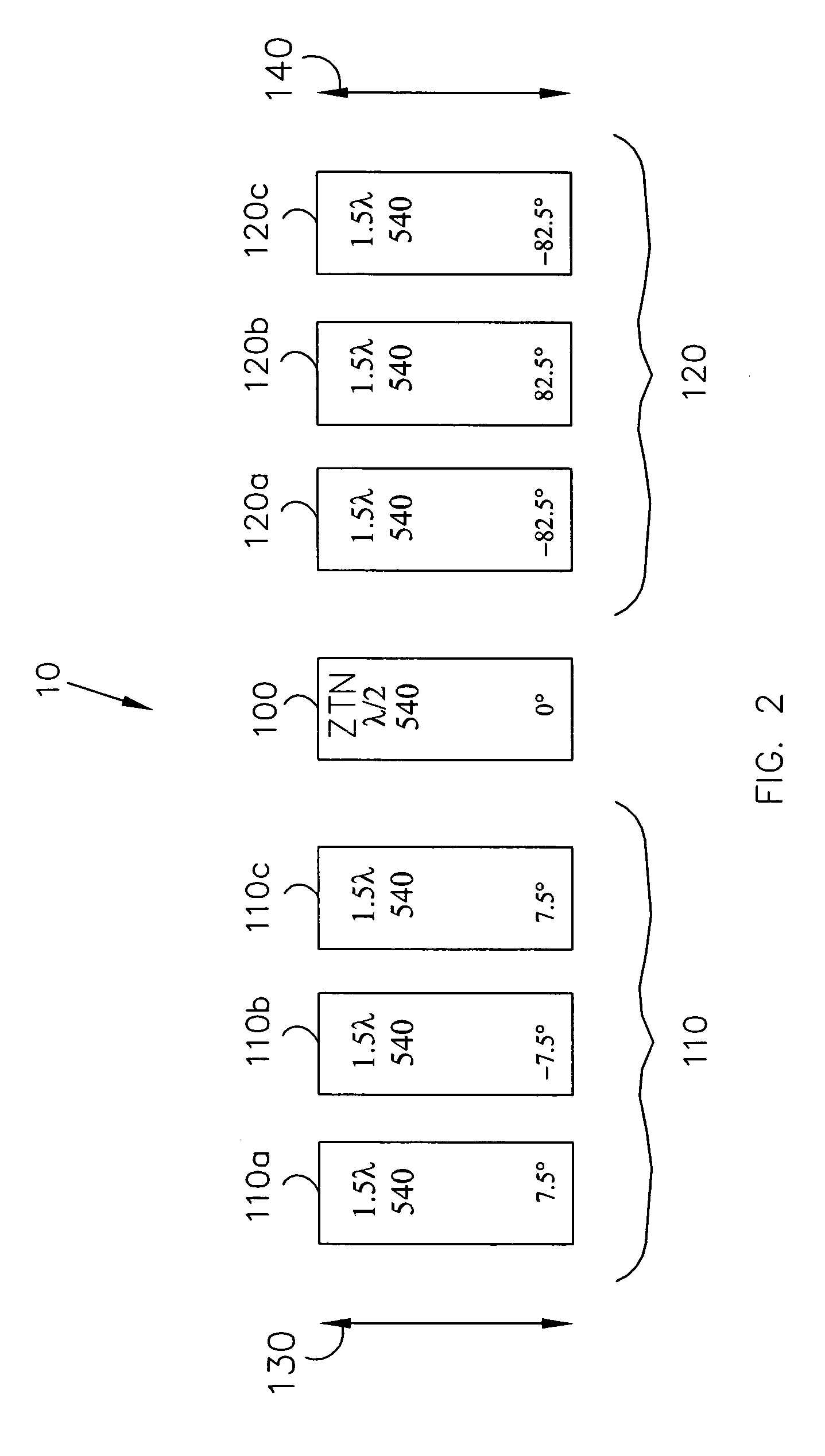
[0130]FIG. 3 magenta / white M / W color filter similar to the color filter shown in FIG. 2, except that the color filter of FIG. 3 transmits a white output in the SA mode. Like the color filter shown in FIG. 2, the ZTN LC modulator 100 is oriented parallel or perpendicular (π / 2) to the input polarizer 130, so that the modulator 100 will modulate 45° polarized light and pass light that is oriented along the polarization axis of the input, polarizer 130 unchanged.

[0131] The first retarder stack 110 comprises individual retarder films 210a, 210b and 210c oriented at 7.5°, −7.5°, and 7.5°, respectively, with respect to the input polarizer 130. The second retarder stack 120 comprises individual retarder films 220a, 220b and 220c oriented at 82.5°, −82.5° and 82.5°, respectively, with respect to the input polarizer 130. The individual retarder films in the first and second retarder stacks 110 and 120 are 1.5-wave retarders i...

embodiment 3

SO Crossed-Stack, π / 4-Oriented ZTN LC Modulator, Crossed Polarizer

[0134]FIG. 4 shows another embodiment of a color filter with a magenta / white output. Like the embodiments shown in FIGS. 2 and 3, the input and exit polarizers 130 and 140 are oriented parallel with respect to each other. However, the ZTN LC half-wave modulator 100 is oriented at the ±π / 4 with respect to the input polarizer 130. Thus, the modulator 100 modulates the polarization of light that is oriented parallel to the polarization axis of the input polarizer 130, and leaves the polarization of light that is oriented at ±π / 4 with respect to the input polarizer 130 unchanged.

[0135] In order to obtain a M / W output like the color filter shown in FIGS. 2 and 3, the first and second retarder stacks 110 and 120 are modified so that they each provide full-wave retardence in the green (140 nanometers). As in the color filter shown in FIG. 2, the first and second retarder stacks 110 and 120 are crossed with respect to each ...

embodiment 4

SA Crossed-Stack, π / 4-Oriented ZTN LC Modulator, Crossed Polarizer

[0137]FIG. 5 shows another embodiment of a CSLM 10 similar to the CSLM shown in FIG. 4, except that a white output is achieved in the SA mode. The ZTN LC half-wave modulator 100 reflects the state of polarization, such that the input polarization appears to be oriented at π / 2, and the first retarder stack 110“appears” to have orientations π / 2−α1, π / 2−α2, . . . π / 2−αN. A SA white state is generated by creating the “appearance” of crossed retarder stacks and parallel polarizers. This is done by orienting the exit polarizer 140 at π / 2, and orienting the individual retarders second retarder stack 120 at −αN, . . . −α1. The resulting structure has first and second retarder stacks 110 and 120 of opposite sign.

[0138] The embodiment shown in FIG. 5, the first retarder stack 110 comprises individual retarders 410a, 410b and 410c, oriented at 22.5°, 75° and −60°, respectively, with respect to the input polarizer 130. The seco...


PUM

PropertyMeasurementUnit
wavelengthaaaaaaaaaa

Abstract

The present invention provides a high brightness color selective light modulator (CSLM) formed by a polarization modulator positioned between two retarder stacks. The modulator changes the apparent orientation of one retarder stack relative to the other so that, in a first switching state of the modulator the two retarder stacks cooperate in filtering the spectrum of input light, and in a second switching state the two retarder stacks complement each other, yielding a neutral transmission spectrum. Two or more CSLM stages can be used in series, each stage providing independent control of a primary color. One preferred embodiment eliminates internal polarizers between CSLM stages, thereby providing an additive common-path full-color display with only two neutral polarizers. Hybrid filters can be made using the CSLMs of this invention, in combination with other active or passive filters. The CSLMs of this invention can be used in many applications, particularly in the areas of recording and displaying color images. They can be arranged in a multi pixel array by pixelating the active elements, and can be implemented as color filter arrays, using patterned passive retarders rather than active polarization modulators.

Description

[0001] This application is a Continuation-In-Part Application of Ser. No. 08 / 645,580, filed May 14, 1996, the contents of which are incorporated herein by reference in their entirety.BACKGROUND OF THE INVENTION [0002] 1. Field of the Invention [0003] This invention relates generally to color selective polarization modulation and, more specifically, to color sequencers for colorizing imaging devices, such as displays and cameras. [0004] 2. Background of the Related Art [0005] Full color display is generally implemented using one of four techniques: (1) spatially using color filter arrays; (2) temporally using sequential color techniques; (3) additive superposition using multiple optical paths; or (4) subtractively using stacked display panels. In spatial color systems, each full-color pixel is subdivided into at least three sub-pixels, one dedicated to each additive primary color. A color filter array (CFA), consisting of red, green and blue spectral filters, is registered to the act...

Claims


Application Information

Patent Timeline
Patent Type & Authority Applications(United States)
IPC IPC(8): G02B27/28G02F1/01G02F1/03G02F1/09G02F1/1335G02F1/13363G02F1/1347G02F1/23H04N5/66H04N5/74H04N9/31
CPCG02B27/288H04N9/3197G02F1/0322G02F1/09G02F1/133533G02F1/133536G02F1/13363G02F1/13473G02F1/23G02F2001/133543G02F2001/133638G02F2413/04G02F2413/08H04N5/66H04N5/7441H04N9/3111H04N9/3167G02F1/0136G02F1/133543G02F1/133638
Inventor SHARP, GARY D.
Owner REAID INC
Why Eureka
Try Eureka