Audio power meter

Inactive Publication Date: 2005-06-09
WALLACE HENRY B
View PDF28 Cites 15 Cited by
  • Summary
  • Abstract
  • Description
  • Claims
  • Application Information

AI Technical Summary

Benefits of technology

[0039] 21. The APM uses a mechanical relay and passive resistors to implement an attenuator that introduce practically zero noise into the signal path.
[0040] The typical arrangement used by musicians is shown in FIG. 1. A musical instrument 10 (electric guitar, electric bass, electric keyboard, voice, recording, or other such source of program material), with optional sound effects processing (not shown), is connected through a shielded signal cable 11 to an audio power amplifier 12. The signal level in the shielded signal cable 11 is approximately 0.5V (volts) RMS (root mean square) to 2V RMS. The audio power amplifier 12 typically has a voltage gain of 30 dB (decibel) to 40 dB, and also has a low output impedance to deliver power to a low impedance speaker 14 (typically 2 ohms to 16 ohms), through a heavy gauge speaker cable 13.
[0041] In audiophile music systems, the amplifier and speaker(s) are intended to pass the program signal without any coloration or distortion. However, musicians typically rely on the amplifier and speaker to contribute unique tone, coloration, and distortion effects to their performances. It is common for musicians to run their amplifiers in or near the clipping region to attain a richer sound than could be had from a low distortion stereophonic type of amplifier and speaker system. Additionally, musical instrument speakers color the sound in different amounts at different input power levels. The musician seeks these colorations and tones in an effort to attain his distinctive sound or reproduce the sound of famous musicians.
[0042] The musician tends to risk damage to the speaker by running it near the rated limit to get a subjectively good sound. If the speaker fails, t

Problems solved by technology

The musician tends to risk damage to the speaker by running it near the rated limit to get a subjectively good sound.
If the speaker fails, then the amplifier can be damaged by high currents or voltages in the

Method used


Image

  • Audio power meter
  • Audio power meter
  • Audio power meter

Examples


embodiment

Preferred Embodiment

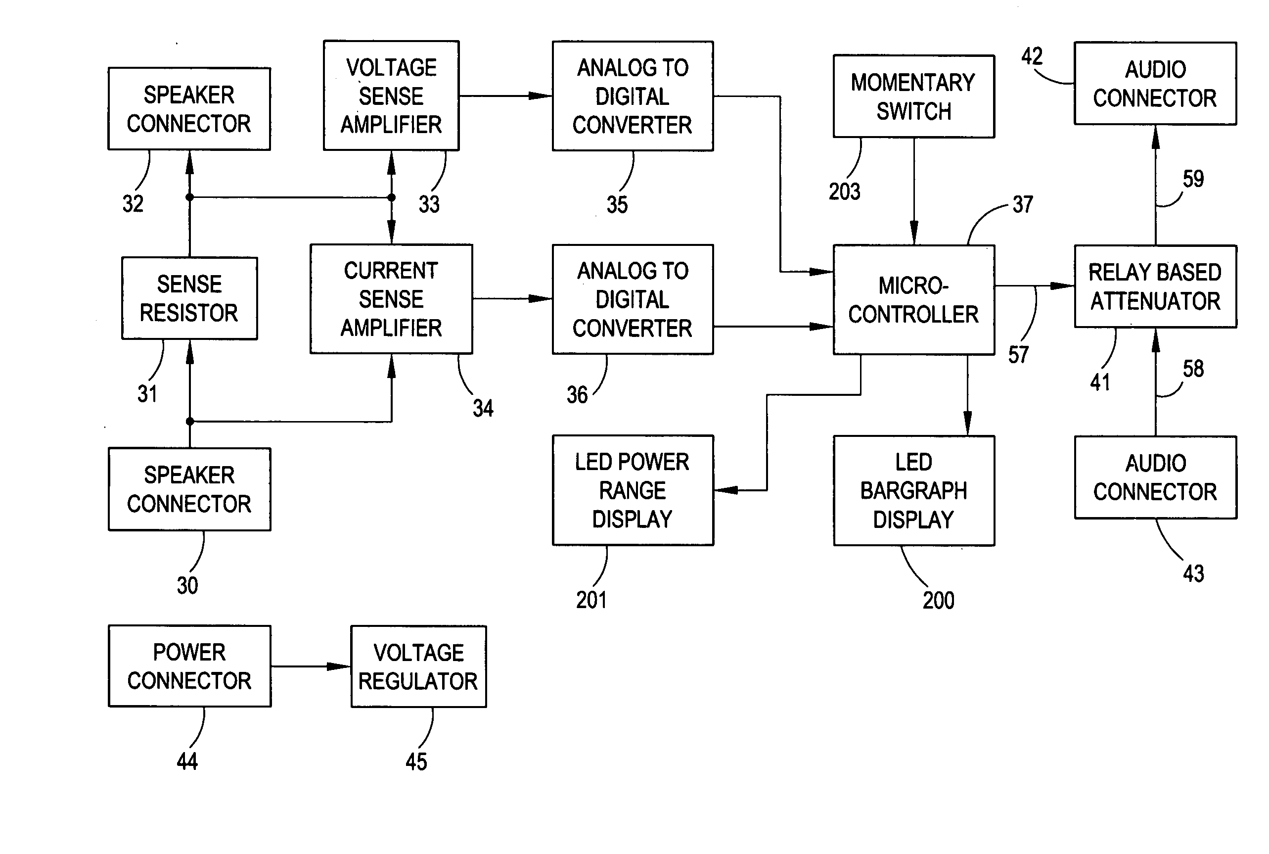
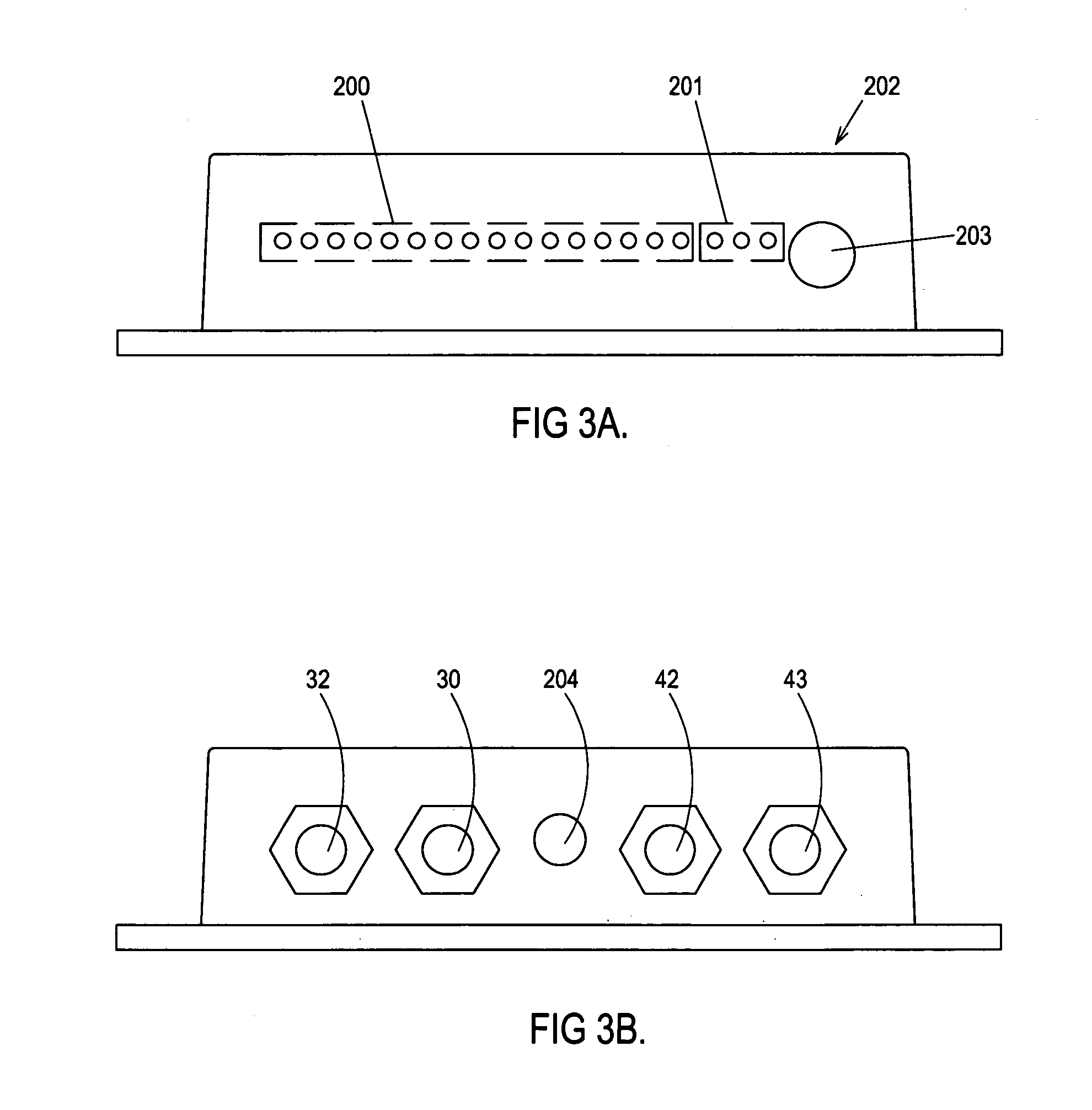
[0090] The functions of the APM are presented in two embodiments, without prejudice against other embodiments carrying functions as claimed. The preferred embodiment (shown in FIG. 3A, front view, and FIG. 3B, rear view) is powered from the AC power mains using an inexpensive conventional wall transformer, and is preferred because musicians generally avoid the use of batteries due to the cost of frequent replacement and the probability of unexpected battery exhaustion. This embodiment can be rack mounted with an additional bracket (not shown), or set on an amplifier or speaker cabinet, or screwed to an equipment carrying case.

[0091] Referring to FIG. 3B, the APM is powered all the while the power cord is plugged in to the power jack 204. Power switching is typically provided by the musician as part of his equipment setup.

[0092] Connections to the APM are made through ¼ inch phone jacks, 30, 32, 42, and 43. The functions and connections of these jacks are descri...


PUM


Abstract

An audio power meter includes a circuit for measuring the power of an amplified audio signal outputted by an audio power amplifier to which the audio power meter is connected. The circuit generates an output signal indicative of the power of the amplified audio signal. A first bar display includes a plurality of separately illuminatable segments arranged linearly with respect to one another. Each segment of the plurality of separately illuminatable segments is responsive to the output signal of the circuit and is selectively illuminated in response thereto. When the measured power of the amplified audio signal exceeds a selected threshold power level, the amplified audio signal is attenuated.

Description

CROSS REFERENCE TO RELATED APPLICATION [0001] This application is a continuation-in-part of U.S. application Ser. No. 10 / 852,035, filed on May 24, 2004, and entitled “True RMS Audio Power Meter”, the disclosure of which is incorporated herein by reference, which prior application claims the benefit of U.S. provisional patent application Ser. No. 60 / 475,575, filed on Jun. 3, 2003, and entitled “True RMS Audio Power Meter”, the disclosure of which is also incorporated herein by reference.CROSS REFERENCE TO DOCUMENT DISCLOSURE [0002] This application refers to, and incorporates, Document Disclosure No. 509276, filed with a Disclosure Document Deposit Request on Mar. 25, 2002 by the inventor herein, and entitled “PM-150 Audio Power Meter”. BACKGROUND OF THE INVENTION [0003] 1. Field of the Invention [0004] The present invention relates to the measurement of power in a system consisting of audio power amplifier(s) (or simply, amplifier) and speaker(s), and a method of protecting the spea...

Claims


Application Information

Patent Timeline
IPC IPC(8): H04R3/00H04R29/00
CPCH04R29/001H04R3/007
Inventor WALLACE, HENRY B.
Owner WALLACE HENRY B
Why Eureka
Try Eureka