
Planetary-harmonic motor

a technology of harmonic motors and planetary plates, applied in the direction of positive displacement engines, reciprocating piston engines, gearing, etc., can solve the problems of magnetic field distortion, artifacts in the image of the patient's body, and difficulty in obtaining accurate images

Inactive Publication Date: 2005-06-09
THE JOHN HOPKINS UNIV SCHOOL OF MEDICINE
View PDF12 Cites 34 Cited by
  • Summary
  • Abstract
  • Description
  • Claims
  • Application Information

AI Technical Summary

Benefits of technology

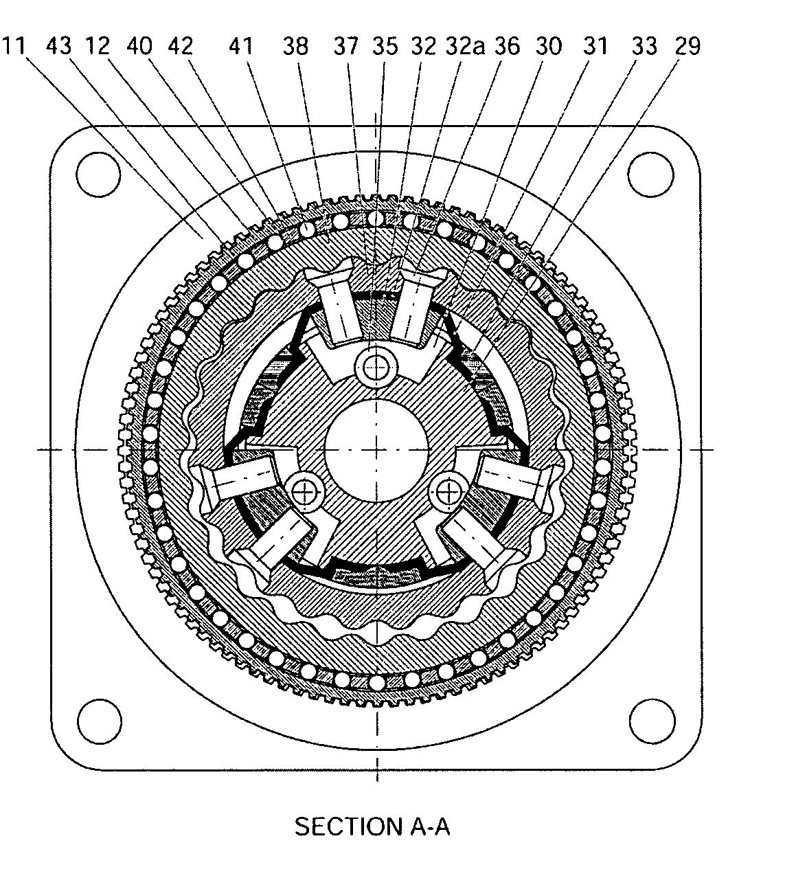
The present invention is a motor designed for use in medical imaging environments. It has a centrally located actuator that causes a flexspline to rotate, which in turn engages with a circular spline and a planetary gear. The actuator can be controlled to move the engagement point as a wave around the inner perimeter of the planetary gear, causing the inner gear to rotate. This design allows for precise control and rotation in medical imaging environments.

Problems solved by technology

However, difficulties are encountered in obtaining accurate images when disruptions and deflections in the magnetic field are experienced due to the presence in the field of materials that produce a magnetic field and / or are susceptible to producing their own magnetic fields when placed within an external magnetic field.
One source of magnetic field distortion can be equipment such as motors that are in the vicinity of the MRI machine.
Thus, when placed in the field generated by the MRI machine, the motors can cause artifacts in the image of the patient's body.
Other forms of medical imaging (e.g., x-ray and ultrasound imagers) are also seen to have similar problems of distortions in their output images due to the presence of motors in the vicinity of the imaging equipment.

Method used


Image

  • Planetary-harmonic motor
  • Planetary-harmonic motor
  • Planetary-harmonic motor

Examples


Embodiment Construction

[0037] Before explaining at least one embodiment of the present invention in detail, it is to be understood that the invention is not limited in its application to the details of construction and to the arrangements of the components set forth in the following description or illustrated in the drawings. The invention is capable of other embodiments and of being practiced and carried out in various ways. Also, it is to be understood that the phraseology and terminology employed herein are for the purpose of description and should not be regarded as limiting.

[0038] In general, the present invention relates to motors that are made with materials that have low magnetic susceptibility and produces minimal, if any, magnetic fields. For example, materials such as plastics, glass, ceramics, rubbers, etc.

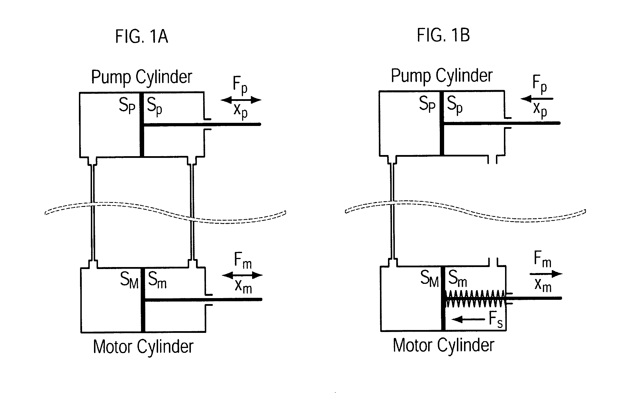
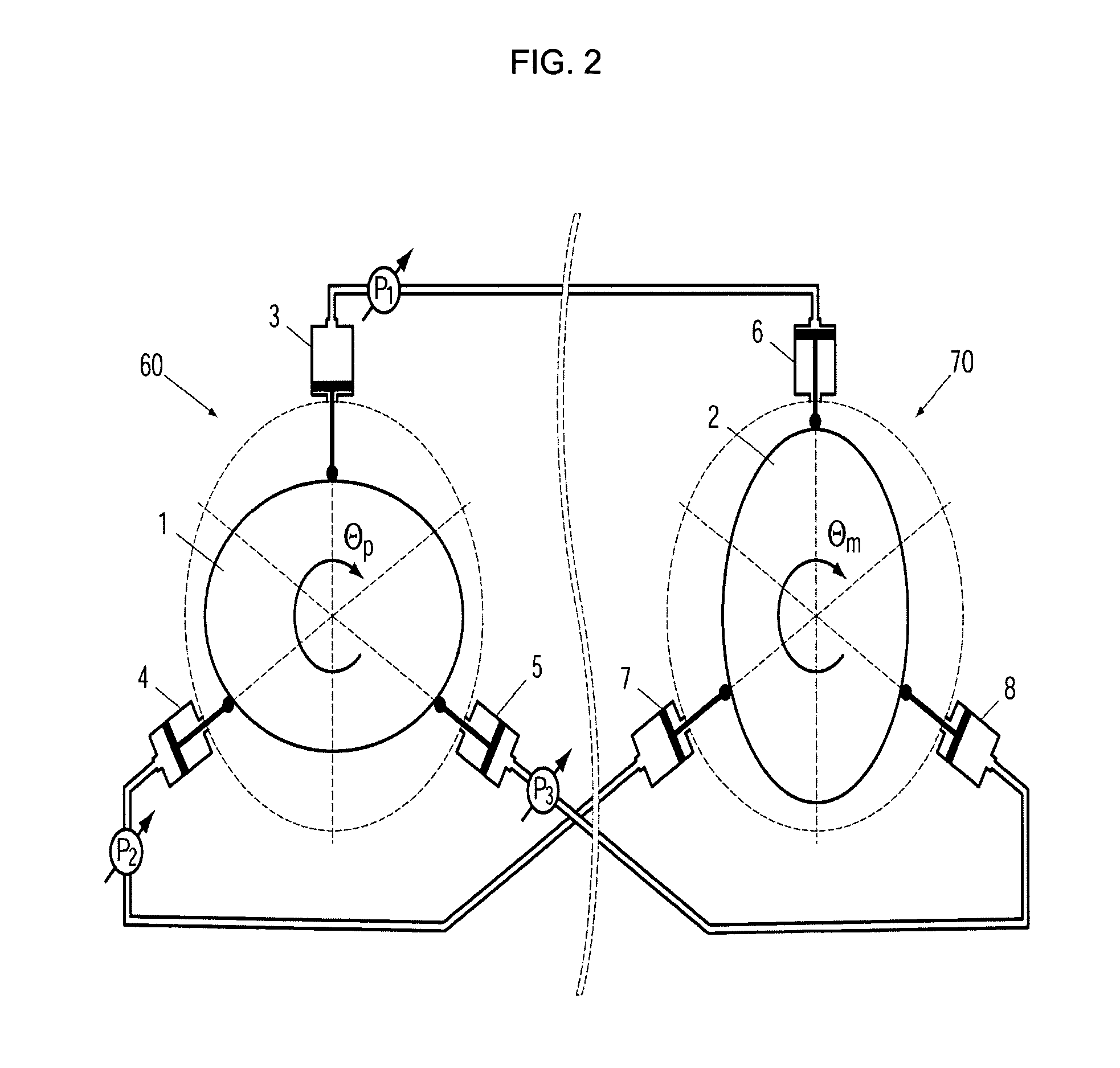
[0039] The invention of the present invention is based on two principles of transmission: (a) the coupled, fluid actuated pistons or cylinders for supplying linear motion at a remote locat...


PUM


Abstract

A motor suitable for use in a medical imaging environment has (a) a centrally located means for actuating a radial wave, (b) a deformable flexspline having an inner surface and a toothed outer surface, with the flexspline coaxially aligned with the central axis of the radial wave actuating means and oriented such that the flexspline inner surface is proximate the outer boundary surface of the actuation means, and with the flexspline toothed outer surface having a first specified number of teeth, and (c) a circular spline having a toothed inner surface, this spline having an outer boundary surface and being coaxially aligned with the central axis and oriented such that the spline toothed inner surface is proximate the flexspline's toothed outer surface, with the spline inner surface having a second specified number of teeth which is different than the first specified number of teeth in the flexspline, wherein the actuation means is operable so that the action of its radial wave causes at least one of the flexspline teeth to engage at a point the toothed side of the circular spline in such a manner that an engagement point passes as a wave around the inner perimeter of the circular spine, with the movement of this engagement point causing the flexspline to rotate around its central axis.

Description

CROSS-REFERENCE TO RELATED APPLICATION [0001] This application claims the benefit of U.S. Provisional Patent Application No. 60 / 411,906, filed Sep. 19, 2002 by Dan Stoianovici and Louis R. Kavoussi.STATEMENT AS TO FEDERALLY SPONSORED RESEARCH [0002] This invention was made with Government support under Grant No. 1 R21 CA88232-01A1 and entitled “Multi-Imager Compatible Robot For Prostrate Access,” which was awarded by the National Institute of Health. The Government may have certain rights in this invention.BACKGROUND OF THE INVENTION [0003] 1. Field of the Invention [0004] This invention relates to motors that provide rotary motion. More particularly, one embodiment of the present invention relates to a motor which is constructed from materials that can be used in all classes of medical imaging equipment and that generates precise, high torque, backlash-free rotary motion without using electricity. [0005] 2. Description of Prior Art [0006] Noninvasive, diagnostic imaging techniques,...

Claims


Application Information

Patent Timeline
Patent Type & Authority Applications(United States)
IPC IPC(8): F03C1/04F16H47/04F16H49/00
CPCF03C1/04Y10T74/19F16H49/001
Inventor STOIANOVICI, DANKAVOUSSI, LOUIS R.
Owner THE JOHN HOPKINS UNIV SCHOOL OF MEDICINE
Learn More