
Port stem marking for catheter placement

a catheter and port stem technology, applied in the field of subcutaneous implantable access ports, can solve the problems of leakage and failure, catheter connection systems that do not allow visual verification of attachment, and the catheter is difficult to determine the amount of catheter engagement onto the port stem, so as to reduce the implantation time, facilitate surgical procedures, and minimize failure.

Inactive Publication Date: 2005-06-09
CR BARD INC
View PDF42 Cites 94 Cited by
  • Summary
  • Abstract
  • Description
  • Claims
  • Application Information

AI Technical Summary

Benefits of technology

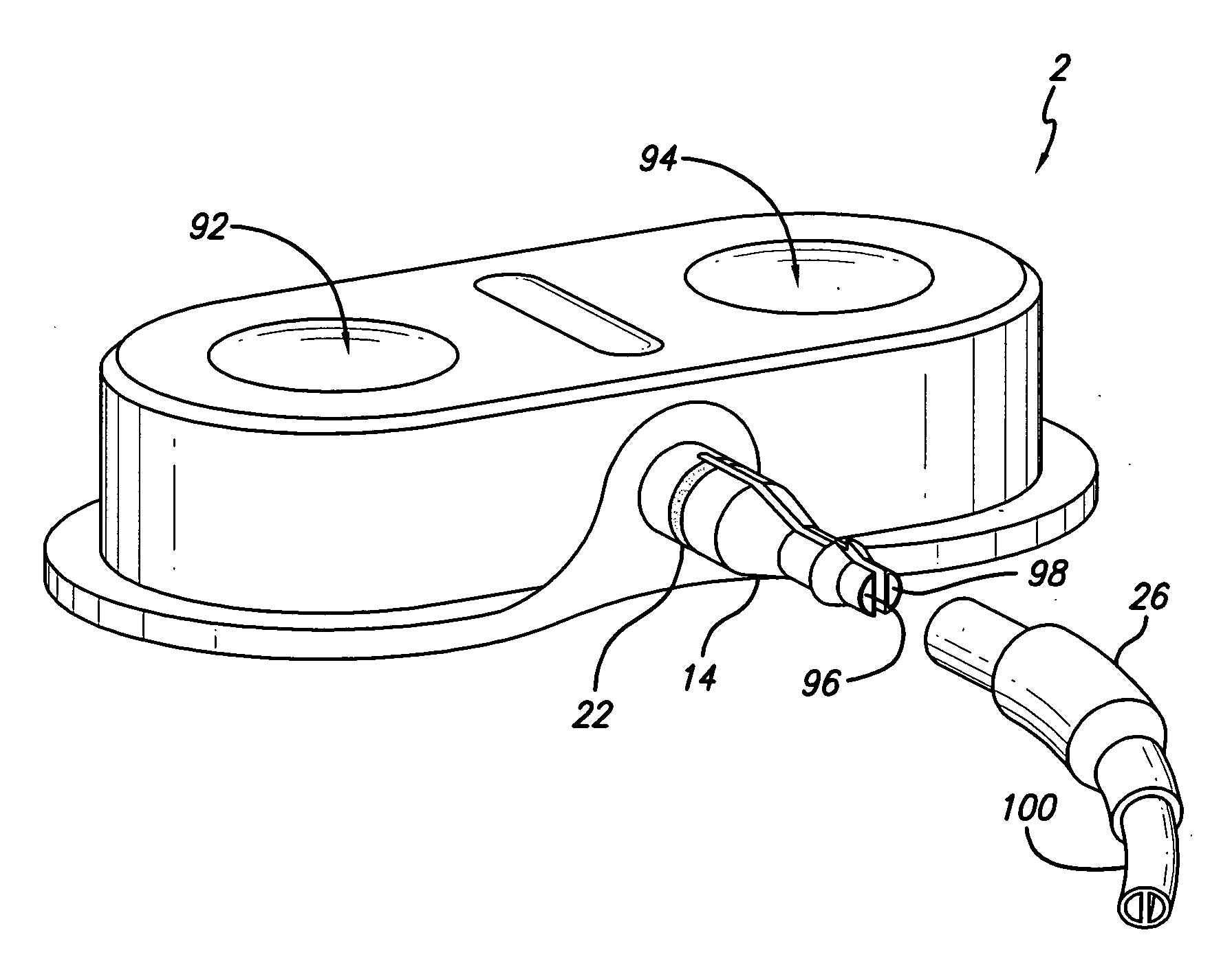
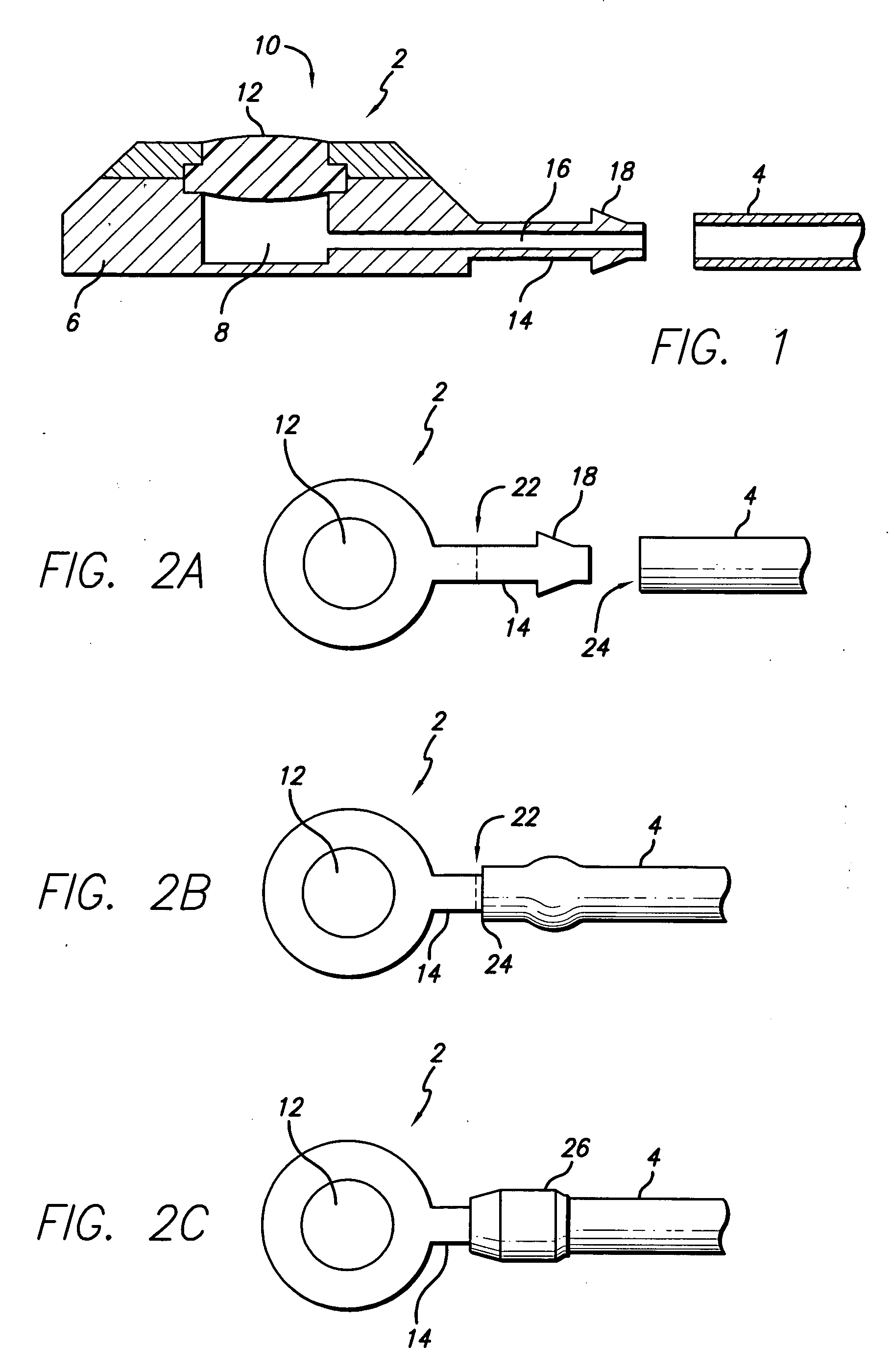
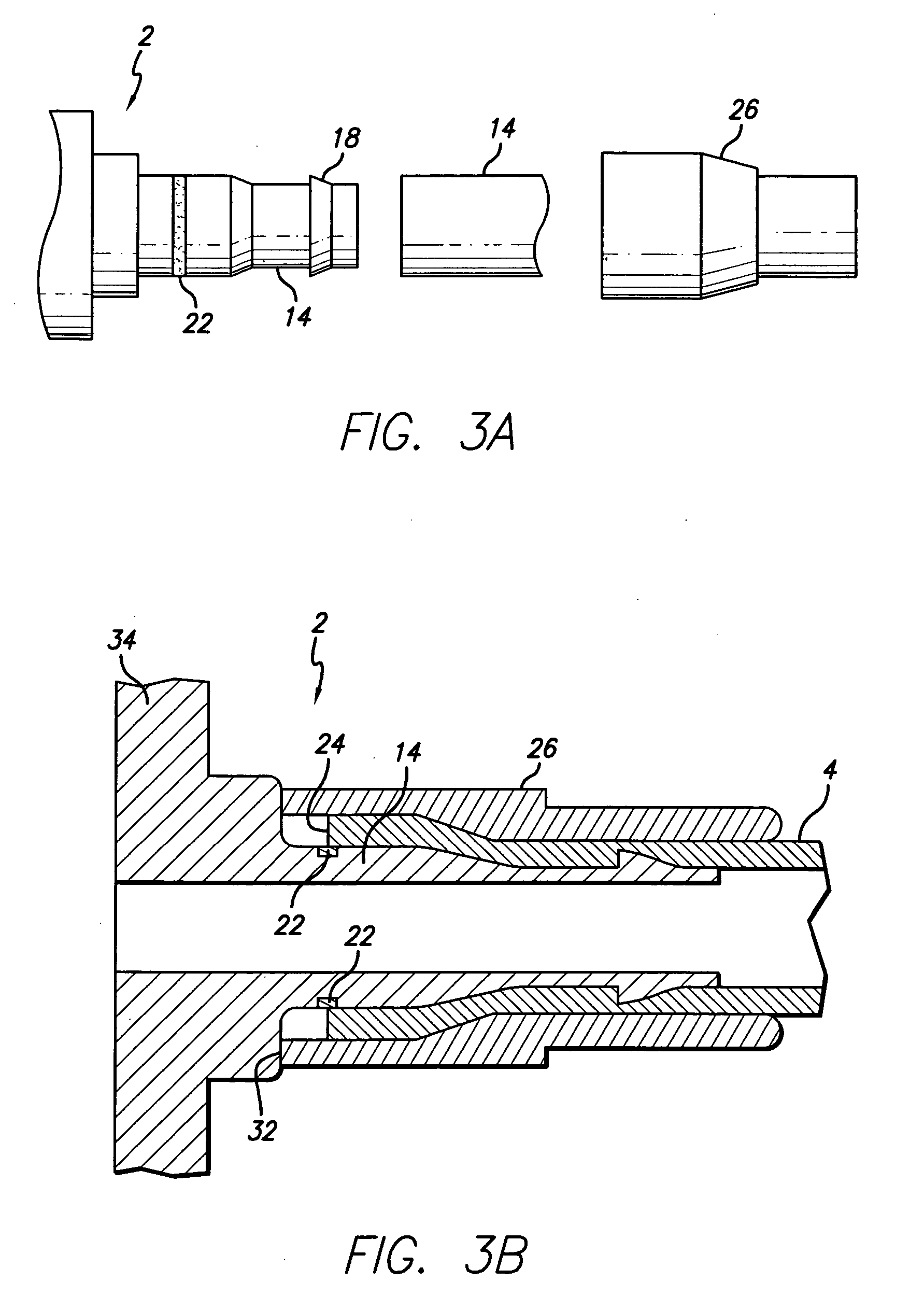
[0014] A marking is provided on the port stem which indicates to the physician the proper distance to advance the port stem into the catheter for optimal connection. The port stem may have one or more barbs on its outer surface to retain the catheter on the port stem. A catheter lock or a locking sleeve may be placed over the catheter and port stem connection to secure the catheter on the port stem. Since the preferred location for the placement of the catheter may vary depending on the design of the port stem or the property of the catheter, such a marker may facilitate consistent placement of the catheter and avoid problems associated with physicians placing the catheter incorrectly (e.g., advancing the catheter to far over or failure to advance the catheter far enough), which could potentially cause in vivo leakage of fluids from the catheter, either due to detachment of the catheter from the port stem, compromise in the catheters integrity, or failure of the seal between the catheter and the port stem.
[0016] Having a marking on the port stem to provide guidance to the surgeons on the placement of the catheter may minimize failure due to inappropriate placement of the catheter. In addition, the marking may also facilitate the surgical procedures for the implantation of the access port since the surgeon may place the catheter onto the catheter with confidence and without the need to repeatedly test and inspect the juncture to be assured that a secured connection has been achieved. Therefore, these benefits may decrease implantation time, reduce failure rate, and decrease overall cost of the procedure for implantation of the access port.

Problems solved by technology

One common problem encountered in the use of access ports relates to the process of connecting the catheter to the access port during the implantation of the access port.
However, it is generally difficult to determine the amount of engagement of the catheter onto the port stem.
For example, some catheter connection systems do not allow visual verification of attachment.
As the result, either due to over-insertion or under-insertion of the port stem into the catheter, leakage and failure can occur.
Because access ports with varying designs are used in today's medical practice, it is not unusual for implanted access ports to fail due to improper connection between the port stem and the catheter.
In some cases, this is due to doctors who advanced the catheter too far on the stem, and in some cases this is due to doctors who do not advance the catheter far enough on the stem.
When the catheter is advanced too far on the stem, there is potential for breakage of the catheter due to pinching and other forces caused by uneven distribution of compression force.
When the catheter is not advanced far enough, the barb on the port stem in combination with the cathlock or locking sleeve may not be able to hold the catheter in place in a robust way.
In either of the above cases, the connection may fail due to incorrect placement of the catheter over the port stem.
While this practice alleviates many of the problems associated with leakage and failure due to catheter slippage, such a system severely limits the type of the catheter usable with the access port.
Furthermore, the cost of providing implant catheters with the desired combination of access ports, catheters, and valves at the distal end of the catheter may increase if the physician must rely on pre fabricated solutions.
Moreover, pre-attached systems eliminate the option of constructing and customizing the access port and catheter combination device based on individual patient's needs.

Method used


Image

  • Port stem marking for catheter placement
  • Port stem marking for catheter placement
  • Port stem marking for catheter placement

Examples


Embodiment Construction

[0037] The detailed description illustrates by way of example, not by way of limitation, the principles of the invention. This description will clearly enable one skilled in the art to make and use the invention, and describes several embodiments, adaptations, variations, alternatives and uses of the invention, including what is presently believed to be the best mode of carrying out the invention. Before describing the present invention, it is to be understood that unless otherwise indicated this invention need not be limited to applications in human. As one of ordinary skill in the art would appreciate, variation of the invention may be applied to other mammals as well.

[0038] A single chamber access port is used herein as an example application to illustrate the functionality of the different aspects of the invention disclosed herein. It will be understood that embodiments of the present invention may be applied in a variety of access ports (e.g., access port with two or more flui...


PUM


Abstract

An access port having a marking located on the port stem to aid the physician in placing the catheter correctly onto the port stem, wherein a fluid channel is provided to allow liquid from the inner lumen of the catheter to flow into the chamber located inside the access port. In one variation, the marking indicates to the physician the proper distance to advance the port stem into the catheter for optimal connection. A catheter lock or other locking sleeves may be placed over the catheter and port stem connection to secure the catheter on the port stem. Since the preferred location for the placement of catheter may differ depending on the design of the port stem, such a marker may facilitate the placement of the catheter and avoid problems associated with physicians placing the catheter incorrectly, which could potentially result in in vivo leakage from the catheter.

Description

CROSS-REFERENCE TO RELATED APPLICATIONS [0001] Not applicable. STATEMENT REGARDING FEDERALLY SPONSORED RESEARCH OR DEVELOPMENT [0002] Not applicable. REFERENCE TO A COMPACT DISK APPENDIX [0003] Not applicable. BACKGROUND OF THE INVENTION [0004] The present invention generally relates to a subcutaneously implantable access port. More specifically, the present invention relates to the use of markers or indicia on an outlet stem of the access port (i.e., port stem) to facilitate proper placement of a catheter thereon. [0005] A variety subcutaneously implantable access ports haven been utilized by physicians to deliver fluids to, or to withdraw fluids from the blood stream or other subcutaneous cavities inside a patient. One example of such an access port includes a needle-impenetrable housing, which encloses one or more fluid cavities and defines for each of such fluid cavity an access aperture communicating through the housing on the side thereof, which is adjacent to the skin of the ...

Claims


Application Information

Patent Timeline
IPC IPC(8): A61M37/00A61K9/22
CPCA61M39/0208A61M2205/32A61M2039/0211
Inventor SANDERS, SCOTT W.
Owner CR BARD INC
Learn More