Sternum fixation device

a fixation device and sternum technology, applied in the field of surgical devices, can solve the problems of sharp ends that can pierce through the surgeon's gloves or fingers, easy to break steel wires, and difficult to maneuver and place around the sternum, and achieve the effect of increasing the pull-out resistance of the fastener

Active Publication Date: 2005-06-09
SYNTHES USA
View PDF80 Cites 175 Cited by
  • Summary
  • Abstract
  • Description
  • Claims
  • Application Information

AI Technical Summary

Benefits of technology

[0010] According to one aspect of the present invention, the release member is a pin, which may be a single pronged pin. The pin may have a splayed apart tip portion. Alternatively, the release member is a two pronged pin, which may be angled with respect to a mating line between the first and second plates. The release member may also be a cam or quarter-turn fastener, and the first and second plates may be provided with matching sets of ratchet teeth that cooperate with the release member to allow the distance between the first and second plates to be varied.
[0011] The attachment member may be a threaded through hole that passes through the second plate upper and sternum-contacting surfaces for receiving a threaded fastener head. To increase pull-out resistance of the fastener, the at least one threaded hole may be angled away from the second plate.

Problems solved by technology

While utilization of steel wires and strap assemblies have been widely accepted for sternum fixation, these devices present a number of disadvantages.
For example, steel wires are susceptible to breakage, are difficult to maneuver and place around the sternum, and often have sharp ends that can pierce through the surgeon's gloves or fingers.
Steel wire and band assemblies also provide insufficient or non-uniform clamping force on the sternal halves, thus resulting in sternal nonunion.
The steel wire and band assemblies also provide insufficient clamping forces in all three planar directions, thus leading to healing problems caused by unwanted bone movements leading to raking and rubbing of the surrounding tissue or bone.
This technique, however, is not optimal because it requires direct fixation of the plates to the bone with screws, making reentry into the thoracic cavity through the sternotomy extremely difficult in case of a medical emergency.
Similar to the use of plates, discussed above, this technique does not provide quick access to the organs and / or tissues within the patient's thoracic cavity.
The ratchet assembly provides quickened accesses to the thoracic cavity, but is cumbersome to use and is limited to the hook-shaped clamp members disclosed.

Method used


Image

  • Sternum fixation device
  • Sternum fixation device
  • Sternum fixation device

Examples


Embodiment Construction

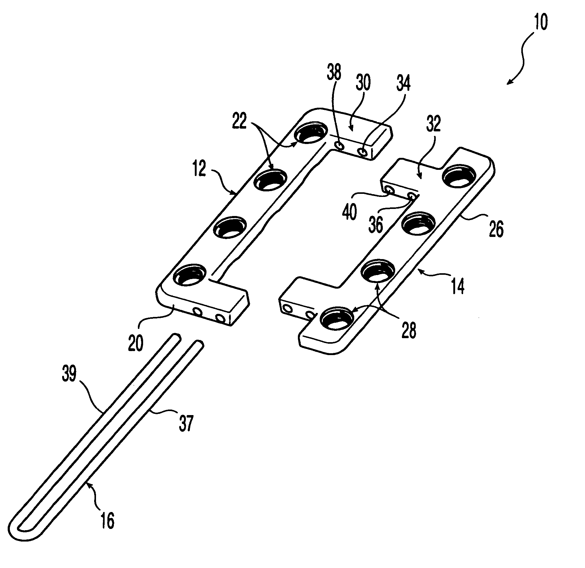
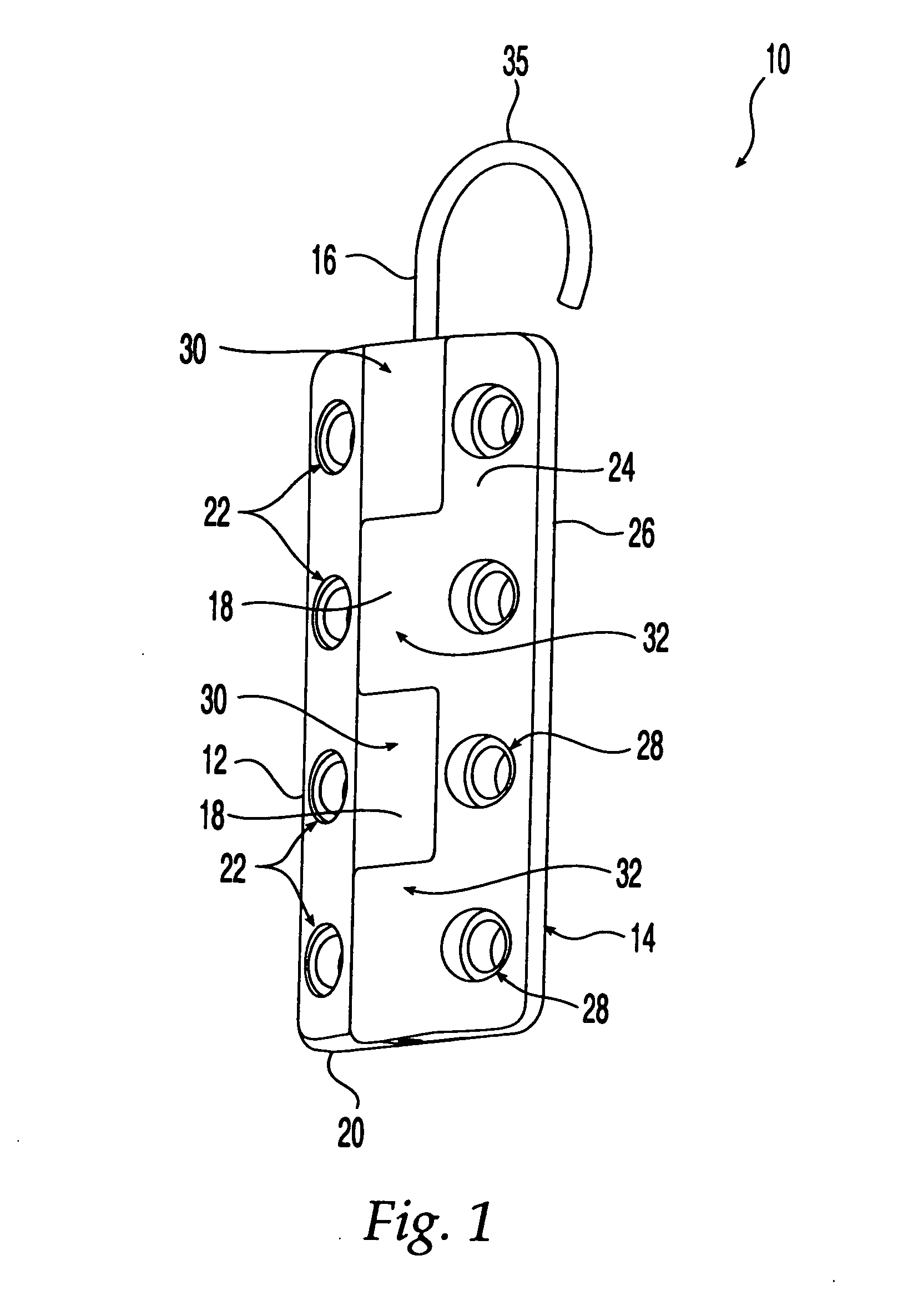
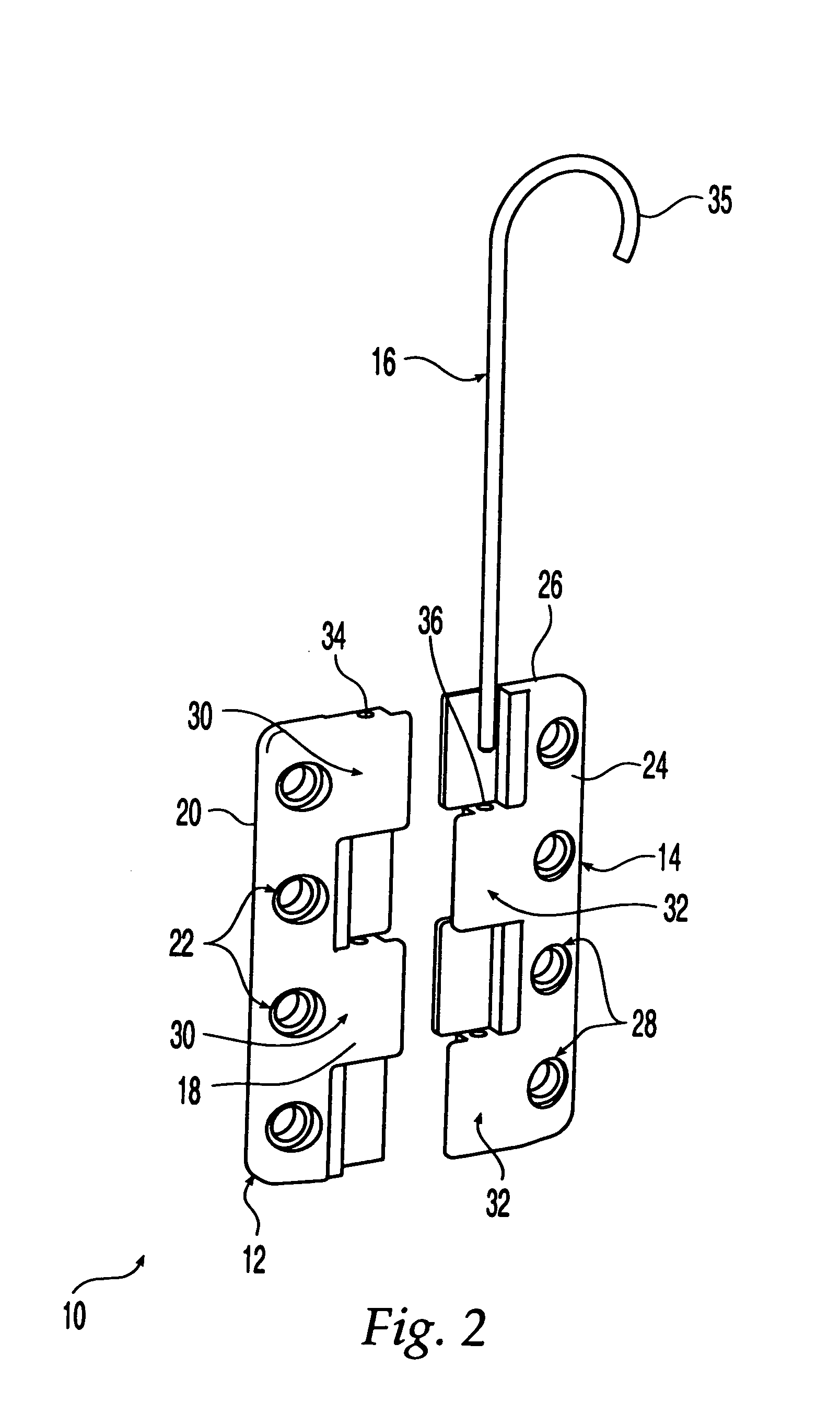
[0029]FIGS. 1 and 2 show a first illustrative embodiment of a sternum fixation device according to the present invention, shown as sternum fixation device 10. Sternum fixation device 10 includes first and second mating plates 12, 14 attached to one another by a release member 16. First plate 12 and second plate 14 may be used to reapproximate, or secure together, two or more parts of a sternum by attaching each plate to a part of the sternum. Sternum fixation device 10 may be constructed from any suitable bio-compatible material including, but not limited to, bioresorbable materials, radio-translucent materials, allograft materials, stainless steel and titanium

[0030] First plate 12 includes an upper surface 18 and a sternum-contacting surface 20, and a first attachment member 22 for attachment to the sternum. First attachment member 22 is shown as a plurality of threaded holes that are configured to receive a threaded head portion 44 of a fastener, such as a bone screw 42, shown in...


PUM


Abstract

A sternum fixation device for securing parts of a sternum includes first and second removably associated plates. The first plate has an upper surface and a sternum-contacting surface, and at least one hole passing through both of these surfaces for receiving a fastener head. The second plate has at least one attachment member for fixation to the sternum. A release member holds the first and second plates together, and is movably associated with at least one of the first and second plates such that it may be moved to allow separation of the two parts of the sternum.

Description

CROSS-REFERENCE TO RELATED APPLICATIONS [0001] This application is a Divisional Application of U.S. patent application Ser. No. 10 / 073,133, filed Feb. 13, 2002, which claims the benefit under 35 U.S.C. § 119(e) of U.S. Provisional Application No. 60 / 270,620, filed Feb. 23, 2001.FIELD OF THE INVENTION [0002] The present invention relates generally to surgical devices, and more particularly, to devices for reapproximating two or more parts of a patient's sternum. BACKGROUND OF THE INVENTION [0003] Many surgical procedures require two or more parts of a sternum to be reapproximated, or fixed together, such as sternal reconstruction and repair of sternal trauma. In addition, various types of surgical procedures are currently performed to investigate, diagnose, and treat diseases involving tissues or organs located in a patient's thoracic cavity, such as the heart and lungs. These procedures typically require a partial or median sternotomy to gain access to the patient's thoracic cavity....

Claims


Application Information

Patent Timeline
Patent Type & Authority Applications(United States)
IPC IPC(8): A61B17/80A61B17/58A61B17/82A61B17/86
CPCA61B17/8009A61B17/8057A61B17/8076Y10S606/905A61B17/823A61B17/863A61B17/8085
Inventor HEARN, JAMES P.
Owner SYNTHES USA
Why Eureka
Try Eureka