Methods and apparatus for rotary machinery inspection

a technology for rotary machinery and inspection methods, which is applied in the field of gas turbine engines, can solve the problems of cracking of blade dovetails, limited knowledge of inspection techniques, and limited ability to assess the integrity of blades. , to achieve the effect of allowing only a limited examination of blades, visual inspection

Active Publication Date: 2005-06-16
GENERAL ELECTRIC CO
View PDF18 Cites 37 Cited by
  • Summary
  • Abstract
  • Description
  • Claims
  • Application Information

AI Technical Summary

Problems solved by technology

During operation, the rotor blade dovetails may be subjected to loading forces that may cause in-service cracking of the blade dovetails.
Known inspection techniques are limited in their ability to assess the integrity of the blade dovetails while the blades are in-

Method used


Image

  • Methods and apparatus for rotary machinery inspection
  • Methods and apparatus for rotary machinery inspection
  • Methods and apparatus for rotary machinery inspection

Examples


Embodiment Construction

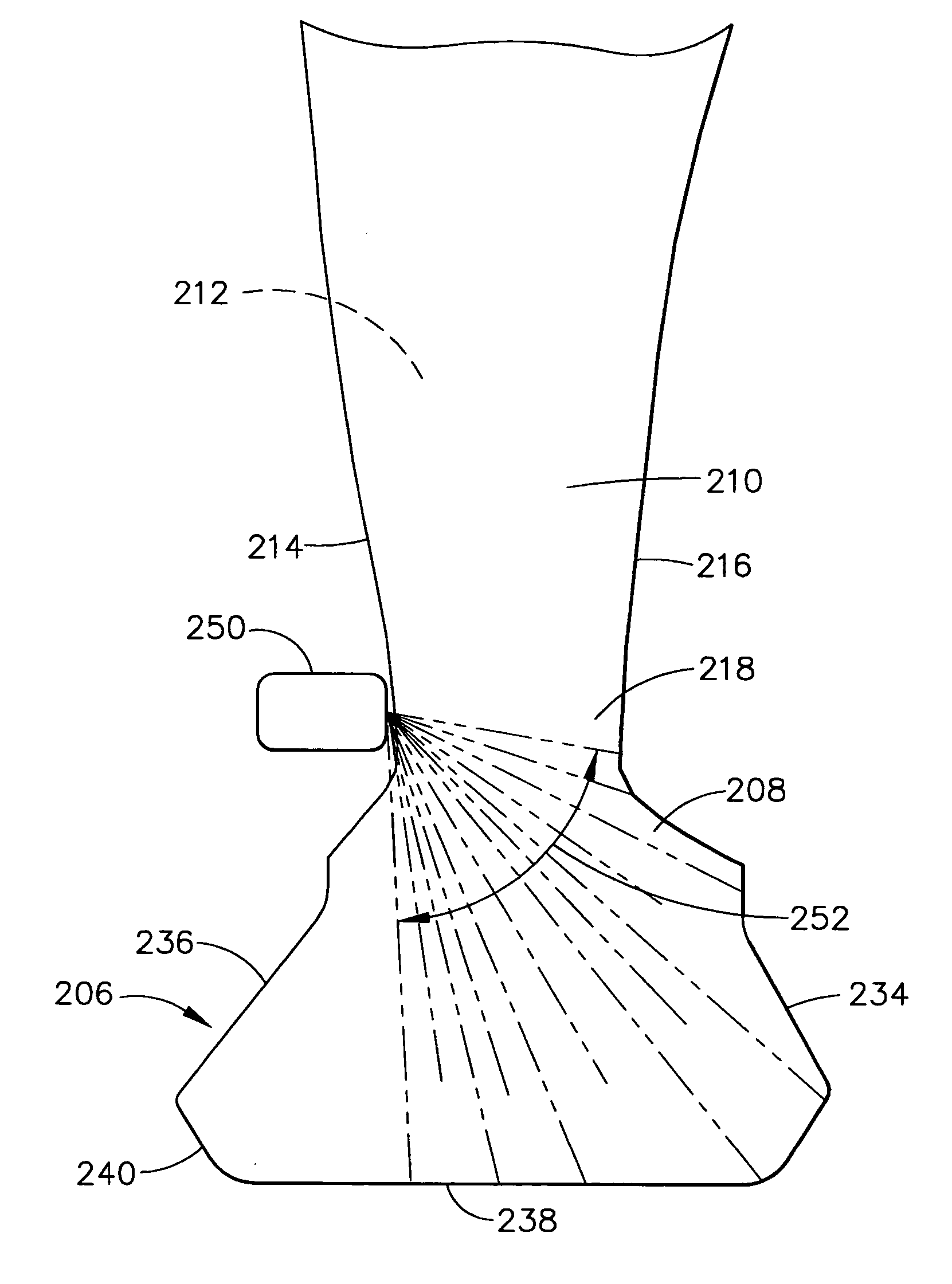
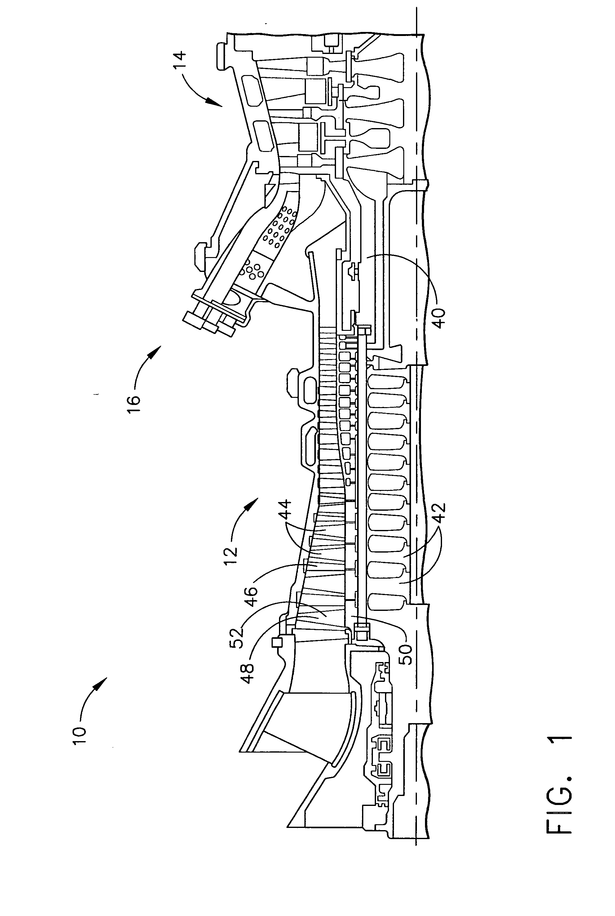
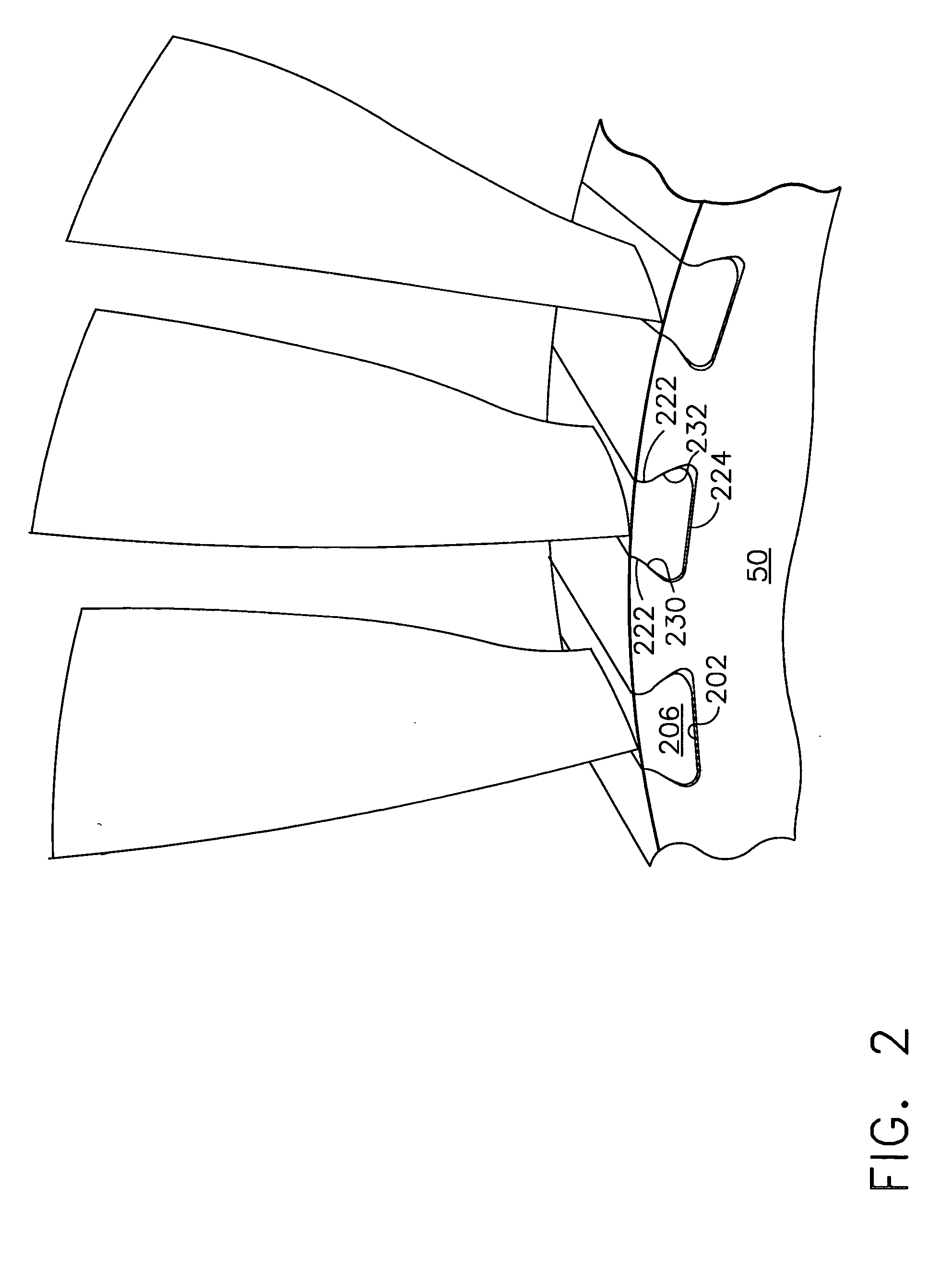
[0015]FIG. 1 is a side elevation view of an exemplary gas turbine engine 10 that includes a compressor section 12, a turbine section 14 and a plurality of combustors 16 (only one combustor shown in FIG. 1) Engine 10 includes a rotor 40 including a plurality of rotor wheels 42. Each rotor wheel 42 is configured to mount a plurality of components, such as, but not limited to, buckets or blades 44, which in conjunction with a respective number of stator vanes 46, form the various stages of engine 10. In the exemplary embodiment, a plurality of compressor blades 44 are coupled to a first row 48 that includes a first-stage rotor wheel 50. Each blade 44 includes an airfoil 52 that is mounted in opposition to respective first-row stator vanes 54. Blades 44 are spaced circumferentially about first-stage wheel 50. Turbine engine 10 may drive a generator (not shown) for producing electrical power. In the exemplary embodiment, engine 10 is a MS6001B gas turbine engine, commercially available f...


PUM


Abstract

A method of non-destructive evaluation (NDE) testing a component of an assembly is provided. The method includes positioning a transducer on a face of the component, transmitting ultrasonic waves into the component at a plurality of steering angles, receiving ultrasonic echoes, wherein each received echo is indicative of an acoustic impedance interface within the component, and analyzing the ultrasonic echoes.

Description

BACKGROUND OF THE INVENTION [0001] This application relates generally to gas turbine engines and, more particularly, to methods and apparatus for testing gas turbine engine compressor and turbine rotor assemblies. [0002] At least some known gas turbine engines include a compressor for compressing air, which is mixed with a fuel and channeled to a combustor wherein the mixture is ignited within a combustion chamber for generating hot combustion gases. The hot combustion gases are channeled downstream to a turbine, which extracts energy from the combustion gases for powering the compressor, as well as producing useful work to propel an aircraft in flight or to power a load, such as an electrical generator. [0003] Known compressors include a rotor assembly that includes at least one row of circumferentially spaced rotor blades. Each rotor blade includes an airfoil that includes a pressure side and a suction side connected together at leading and trailing edges. Each airfoil extends rad...

Claims


Application Information

Patent Timeline
IPC IPC(8): G01N29/04G01N29/265G01N29/28
CPCG01N29/265G01N29/28G01N2291/2693G01N2291/044G01N2291/101G01N2291/018
Inventor CZERW, GERALD JOHNDONOVAN, LAURIE DIANE
Owner GENERAL ELECTRIC CO
Why Eureka
Try Eureka